
Hydro mechanical servo system pdf
A common positional hydraulic servo system is presented in Fig. 2. It is composed of It is composed of a double-acting hydraulic cylinder, designated as 1.0 and a proportional valve 5/3 desig-
involves declutching the mechanical system when it is not in use. To get a fly-by-wire system from a pseudo fly-by-wire system, one needs only to remove the mechanical flight control system entirely.
Our analysis shows that pneumatic systems are practical for use in servo-control applications. The main limitation is that of the system response time, which is determined by the valve flow characteristics and supply pressure. Large output forces can be obtained and accurately controlled with the servo-valve and differential pressure transducer used in the experiments.
SHA Servo-Hydraulic Actuator Electro-hydraulic Electro-mechanical – EMC Compact design Distributed design Single rod cylinder Double rod cylinder –Multiple-area principle Industry-specific Closed system – SHA Open system (Atmosphaeric reservoir) Single rod Double rod cylinders –multi-chamber principle (X=Y+Z) cylinder Double rod Synchronous Discrete multi-chamber Tandem …
In its simplest form a servo or a servomechanism is a control system which measures its own output and forces the output to quickly and accurately follow a command signal, se Figure 1-1 .
Servo press with linear motor drive system: This press system is shown in Fig. 6c and could only be applied to presses with small forces up to 100 kN, which can be used for micro-forming operations. As they omit all kinds of mechanical gears, the predefined path can be followed very exactly to within microns (see Wegener and Schepp 2000 ).
A comprehensive model of a closed-loop servo-valve controlled hydro-motor drive system has been made using Bondgraph simulation technique (Thoma, 1990) [17].
hydro-mechanical spring clamping systems by JAKOB Antriebstechnik.
The hydro-mechanical servo actuator system response can be degraded by the hydraulic fluid, when used as power transmission medium. The study consisted on modeling the servo actuator system, which considers non-linear
DESIGN OF A HYDRAULIC SERVO SYSTEM FOR ROBOTIC MANIPULATION Martin CHOUX and Geir HOVLAND University of Agder Department of Engineering Sciences/Mechatronics
Chapter 2: Hydro-Mechanical versus Electro-Hydraulic Solutions, 43 2.1- Features and Challenges of Electro-Hydraulic Systems, 44 2.2- Pressure Control Solutions, 46
M2 servo system has advanced anti vibration function which include anti resonance and vibration damping. Anti resonance uses two notch filters to overcome the resonance from the natural mechanical characteristic of the system. Vibration damping uses an adjustable damping ratio in the controller to improve the damping characteristic of the system, which can reduce the vibration of the system.
Electro-Hydraulic Servo Valve Construction, Models and Use From Merritt, H. E., Hydraulic Control Systems, J. Wiley, 1967. The input to an electro-hydraulic (EH) servovalve …
active redundant actuation system involving servo-hydraulic and electro-mechanical technologies Lijian Wang and Jean-Charles Mare´ Abstract The force equalization of a hybrid actuation system combining one servo-hydraulic actuator and one electro-mechanical actuator operated in position control and in active/active mode is addressed for safety critical applications such as primary flight
The mechanical system and the control system are the primary novel parts for developing a 3D parallel mechanism robot. In the mechanical system, a 3D parallel mechanism robot contains three serial chains, a fixed base, a movable platform and a pneumatic servo system. The parallel mechanism are designed and analyzed first for realizing a 3D motion in the X-Y-Z coordinate system of the robot’s
Press Brake Artizono

Forming Presses (Hydraulic Mechanical Servo) SpringerLink
Servo presses have recently come into prominence for sheet metal forming operations due to their flexibility, controllability, and simplicity.
SERVO-i® features all the ventilator modes you would expect from an advanced ventilation system, with a number of competitive features. Enhanced interaction It further provides clinicians with proper tools to evaluate the impact of your ventilatory strategy, both over time and during the critical phase associated with interventions.
Hydro-mechanical stone protection SERVO NOVA. 9 Proven system With its variable hydraulic triggering pressure, the SERVO NOVA system adapts the plough to different soil types. Each pair of plough bodies has its own hydraulic accumulator which allows upward movement of up to 40 cm. The lubricated pivot points and additional shear bolts guarantee a long service life. The central filling system
Hydro-mechanical stone protection SERVO NOVA. 9 Proven system With its variable hydraulic triggering pressure, the SERVO NOVA system adapts the plough to different soil types. Each pair of plough bodies has its own hydraulic accumulator which allows upward movement to the side by up to 15.74 inch / 40 cm. The lubricated pivot points and additional shear bolts guarantee a long service …
This method makes the flow-press servo valve as a flow compensation tache, and changes the electro-hydraulic force servo system with strong position disturbance to the electro-hydraulic force
The servo system and hydraulic compensation mechanism provide the speed and precision. 1, Special numeric-control system is fitted with mainframe of the hydraulic cnc metal plate bending machine.
developed mechanical power with respect to the turbine speed, gate opening and runner blade movement of hydro turbine are considered for modeling of the system.
energy, the servo system (Figures 2 and 3). The servo system consists of a servo-valve, hydraulic ducts, The servo system consists of a servo-valve, hydraulic ducts, hydro-motor and the sensors for angular velocity and angle.
Servo System Motion Profile Mechanical Transmission Load Desired Load Velocity Required Motor Torque time How to select and apply SureServo systems Speed (r.p.m.) 300% 200% 100% Torque 1000 2000 3000 4000 5000 Continuous Operating Region Intermittent Operating Region Peak Torque Limited by Current Li mit Peak Torque Limited by Voltage Li t AC Servo Systems 2. Torque and speed With …
Turbines and speed governors Hydraulic turbines Hydraulic turbines Action (or impulse-type) turbines The potential energy of water is converted into pressure and then into kinetic
A hydro-mechanical power transmission according to claim 13 wherein said first rotor means includes a rotor and a shaft driven by said rotor and having said camming surface formed thereon for mechanical communication with said at least one positive and variable displacement pump.
The hydro-mechanical servo displacement control maintains the selected swash plate position and hence pumps displacement. Upon release of the control handle, the swash plate automatically returns to zero position and the
Figure 10.10 shows a mechanical hydraulic servo system with automotive power steering, the sequential operation of which occurs as follows: • The input or …
Electronic current limiting is not a 100% effective way to prevent overloads in a mechanical system R+W Coupling Technology On a servo drive system it is relatively easy to set torque limits in the parameter programming of the machine.
method for aircraft control system. Mechanical & Hydro-mechanical flight control systems have been replaced by Fly-By-Wire due to increasing speed of modern aircraft. Due to inherent characteristics of FBL like light weight, compact size, large bandwidth, immunity to EMI & HIRF FBL, it is expected to be ideal futuristic flight control system. Fly-by-Light control systems offer inherent
Modelling and control of a hydraulic servo system H in Mechanical Engineering at the Eindhoven University of Technology. Trying to combine theory and practice at the one hand and hydraulics and control at the other hand, electro hydraulic servo control is a good base for a multi disciplinary graduation project. On the one hand, the assignment consists of the modelling of a hydraulic system
For the NC press brake, we provide the E21, E200P and DA41s controller which equipped with inverter or servo system. For CNC press brake, we provide DA52s, DA66T and CybTouch series controller. If you have special requirements for the controller, we will discuss …
Hydromechanical System Modelling Using Simscape Simhydraulics – Free download as PDF File (.pdf), Text File (.txt) or read online for free.
11/04/2016 · Servo systems – Hydro Mechanical servo systems, Electro hydraulic servo systems and proportional valves. Deceleration circuit, hydrostatics transmission circuits, control circuits for reciprocating drives in machine tools, Material handling equipments.
A common type of servo provides position control. Commonly, servos are electrical, hydraulic or pneumatic. They operate on the principle of negative feedback, where the control input is compared to the actual position of the mechanical system as measured by some type of transducer at the output.
12 Hydro-Mechanical Coupling in Unstable Aircraft Braking Systems 107 Fig. 12.2 Schema of the hydraulic circuit account. More generally, for industrial systems with hydraulic circuits, the identification of the dynamic contribution of the
Our servo deep draw press line up is our most versatile series. Tonnage, speeds, die area, side openings in frame, slide stroke & daylight, cylinder arrangement, cushions, ejectors, rolling bolsters are considered based on user application.
The Hydraulic Infinite Linear Actuator, HILA, has been presented in previous publications. The novel actuator consists of one, two or more double-acting cylinders with a common piston rod and
Hydro-Mechanical Coupling in Unstable Aircraft Braking Systems
Mechanical Drive 2 Suction Line 3 Pump 4 Pressure Line 5 Return Line 6 Pressure Valves A Excessive Noises 1. coupling wrongly aligned 2. coupling loose 3. coupling defective 4. loose mounting n pump and/or motor defective 5. other transmission elements loose 6. pump or motor defective 7. wrong direction of rotation 8. noise damping not incorporated in design Suction line resistance because: 1
The tool clamping system in mechanical which make it much safer for workers to change the punch. High-precision Backgauge System The high-precision motorized backgauge adopt precision ball screw and rod which driven by high performance motor in order to guarantee positioning accuracy.
The hydromechanical resonant frequency (HRF) of a valve-cylinder circuit is an interesting concept and an important value to know. If a cylinder is stroking, and its control valve suddenly shifts to block flow, the cylinder and its load will vibrate, usually with considerable … – mechanical engineer interview hr questions and answers pdf pump which delivers hydraulic energy (located at the adjoining room), the servo system (Figures 3.1 and 3.2) and the electrical patch with the outputs of the sensors …
In this pending application I disclosed the use of torque motors, more particularly torque motors coupled with a damping generator, in hydro-electric servo controls in which the final position of the hydraulic device is defined by a control voltage, known as the input voltage, the output movement of the hydraulic device being marked by an output voltage providing the feed back possibly in
7/03/2004 · Skytrucker, Firstly the HMU(heart of the system), The electronic engine control(EEC) sends control signals to servo systems in the Hydromechanical unit (HMU).The electro-hydraulic servo valves (EHSV`s) in the HMU change these signals to hydraulic fuel pressure for these components:
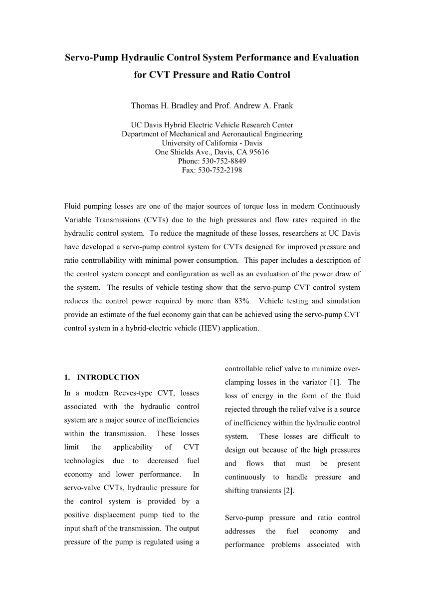
conventional CVTs by reducing control system power draw. In addition, a servo-pump control system can exhibit good controllability, and hydraulic and electrical
The hydraulically servo-steering is a complex pursuit system in accordance to a co-ordinate, having numer- ous clearances, elasticity, compressibility, slits, inter-
The hydro-mechanical servo displacement control maintains the selected swash plate position and hence pump displacement. The low noise level, the high ratio power / …
a.k.a. Split Torque, Power Split, Hydro- mechanical, Electro- mechanical etc. • A variator is a device that can vary the speed or torque ratio across its two shafts in a continuous manner.
Flight Control Systems! 47 Mechanical and Augmented Control Systems •!Mechanical system –!Push rods, bellcranks, cables, pulleys •!Power boost –!Pilot’s input augmented by hydraulic servo that lowers manual force •!Fully powered (irreversible) system –!No direct mechanical path from pilot to controls –!Mechanical linkages from cockpit controls to servo actuators 48. Stability
Other mechanical engine parameters that are sensed are compressor discharge pressure, burner pressure, exhaust temperature, and inlet air temperature and pressure. Once the computing section determines the correct amount of fuel flow, the metering section through cams and servo valves delivers the fuel to the engine fuel system. Actual operating procedures for a hydromechanical fuel control is
A hydro-mechanical flight control system has two parts: The mechanical circuit , which links the cockpit controls with the hydraulic circuits. Like the mechanical flight control system, it consists of rods, cables, pulleys, and sometimes chains.
Hydro Mechanical Units PPRuNe Forums
Electro-Hydraulic Components and Systems Hydraulic

Hydraulic Servo Systems pdfs.semanticscholar.org
GUIDE VANE POSITION CONTROL OF THE MINI HYDRO POWER

Series 20 Axial Piston Pumps Technical Information Danfoss
ELEC0047 Power system dynamics control and stability


SERVO poettinger.at
Hydromechanical System Modelling Using Simscape
– Accurate mathematical model for describing
US5596872A Hydro-mechanical power transmission – Google

Why Use Mechanical Torque Limiters in a Servo Drive System
Electro-hydraulic Servo System (Version B) hs-e uni-due.de
US3025879A Hydro-electric servo mechanisms – Google Patents
Electro-Hydraulic Components and Systems Hydraulic
Figure 10.10 shows a mechanical hydraulic servo system with automotive power steering, the sequential operation of which occurs as follows: • The input or …
developed mechanical power with respect to the turbine speed, gate opening and runner blade movement of hydro turbine are considered for modeling of the system.
For the NC press brake, we provide the E21, E200P and DA41s controller which equipped with inverter or servo system. For CNC press brake, we provide DA52s, DA66T and CybTouch series controller. If you have special requirements for the controller, we will discuss …
A common type of servo provides position control. Commonly, servos are electrical, hydraulic or pneumatic. They operate on the principle of negative feedback, where the control input is compared to the actual position of the mechanical system as measured by some type of transducer at the output.
The hydro-mechanical servo displacement control maintains the selected swash plate position and hence pump displacement. The low noise level, the high ratio power / …
Turbines and speed governors Hydraulic turbines Hydraulic turbines Action (or impulse-type) turbines The potential energy of water is converted into pressure and then into kinetic
Our analysis shows that pneumatic systems are practical for use in servo-control applications. The main limitation is that of the system response time, which is determined by the valve flow characteristics and supply pressure. Large output forces can be obtained and accurately controlled with the servo-valve and differential pressure transducer used in the experiments.
involves declutching the mechanical system when it is not in use. To get a fly-by-wire system from a pseudo fly-by-wire system, one needs only to remove the mechanical flight control system entirely.
Modelling and control of a hydraulic servo system H in Mechanical Engineering at the Eindhoven University of Technology. Trying to combine theory and practice at the one hand and hydraulics and control at the other hand, electro hydraulic servo control is a good base for a multi disciplinary graduation project. On the one hand, the assignment consists of the modelling of a hydraulic system
11/04/2016 · Servo systems – Hydro Mechanical servo systems, Electro hydraulic servo systems and proportional valves. Deceleration circuit, hydrostatics transmission circuits, control circuits for reciprocating drives in machine tools, Material handling equipments.
Hydro-mechanical stone protection SERVO NOVA. 9 Proven system With its variable hydraulic triggering pressure, the SERVO NOVA system adapts the plough to different soil types. Each pair of plough bodies has its own hydraulic accumulator which allows upward movement of up to 40 cm. The lubricated pivot points and additional shear bolts guarantee a long service life. The central filling system
Hydro-mechanical stone protection SERVO NOVA. 9 Proven system With its variable hydraulic triggering pressure, the SERVO NOVA system adapts the plough to different soil types. Each pair of plough bodies has its own hydraulic accumulator which allows upward movement to the side by up to 15.74 inch / 40 cm. The lubricated pivot points and additional shear bolts guarantee a long service …
SERVO-i maquet.com
HYDRAULIC FLUID VALIDATION THROUGH MODELING AND
Turbines and speed governors Hydraulic turbines Hydraulic turbines Action (or impulse-type) turbines The potential energy of water is converted into pressure and then into kinetic
The hydromechanical resonant frequency (HRF) of a valve-cylinder circuit is an interesting concept and an important value to know. If a cylinder is stroking, and its control valve suddenly shifts to block flow, the cylinder and its load will vibrate, usually with considerable …
a.k.a. Split Torque, Power Split, Hydro- mechanical, Electro- mechanical etc. • A variator is a device that can vary the speed or torque ratio across its two shafts in a continuous manner.
developed mechanical power with respect to the turbine speed, gate opening and runner blade movement of hydro turbine are considered for modeling of the system.
A common type of servo provides position control. Commonly, servos are electrical, hydraulic or pneumatic. They operate on the principle of negative feedback, where the control input is compared to the actual position of the mechanical system as measured by some type of transducer at the output.
The servo system and hydraulic compensation mechanism provide the speed and precision. 1, Special numeric-control system is fitted with mainframe of the hydraulic cnc metal plate bending machine.
Hydro-mechanical stone protection SERVO NOVA. 9 Proven system With its variable hydraulic triggering pressure, the SERVO NOVA system adapts the plough to different soil types. Each pair of plough bodies has its own hydraulic accumulator which allows upward movement of up to 40 cm. The lubricated pivot points and additional shear bolts guarantee a long service life. The central filling system
hydro-mechanical spring clamping systems by JAKOB Antriebstechnik.
12 Hydro-Mechanical Coupling in Unstable Aircraft Braking Systems 107 Fig. 12.2 Schema of the hydraulic circuit account. More generally, for industrial systems with hydraulic circuits, the identification of the dynamic contribution of the
SHA Servo-Hydraulic Actuator Electro-hydraulic Electro-mechanical – EMC Compact design Distributed design Single rod cylinder Double rod cylinder –Multiple-area principle Industry-specific Closed system – SHA Open system (Atmosphaeric reservoir) Single rod Double rod cylinders –multi-chamber principle (X=Y Z) cylinder Double rod Synchronous Discrete multi-chamber Tandem …
method for aircraft control system. Mechanical & Hydro-mechanical flight control systems have been replaced by Fly-By-Wire due to increasing speed of modern aircraft. Due to inherent characteristics of FBL like light weight, compact size, large bandwidth, immunity to EMI & HIRF FBL, it is expected to be ideal futuristic flight control system. Fly-by-Light control systems offer inherent
DESIGN OF A HYDRAULIC SERVO SYSTEM FOR ROBOTIC MANIPULATION Martin CHOUX and Geir HOVLAND University of Agder Department of Engineering Sciences/Mechatronics
In this pending application I disclosed the use of torque motors, more particularly torque motors coupled with a damping generator, in hydro-electric servo controls in which the final position of the hydraulic device is defined by a control voltage, known as the input voltage, the output movement of the hydraulic device being marked by an output voltage providing the feed back possibly in
Our analysis shows that pneumatic systems are practical for use in servo-control applications. The main limitation is that of the system response time, which is determined by the valve flow characteristics and supply pressure. Large output forces can be obtained and accurately controlled with the servo-valve and differential pressure transducer used in the experiments.
GUIDE VANE POSITION CONTROL OF THE MINI HYDRO POWER
Hydromechanical System Modelling Using Simscape
Servo presses have recently come into prominence for sheet metal forming operations due to their flexibility, controllability, and simplicity.
a.k.a. Split Torque, Power Split, Hydro- mechanical, Electro- mechanical etc. • A variator is a device that can vary the speed or torque ratio across its two shafts in a continuous manner.
Flight Control Systems! 47 Mechanical and Augmented Control Systems •!Mechanical system –!Push rods, bellcranks, cables, pulleys •!Power boost –!Pilot’s input augmented by hydraulic servo that lowers manual force •!Fully powered (irreversible) system –!No direct mechanical path from pilot to controls –!Mechanical linkages from cockpit controls to servo actuators 48. Stability
method for aircraft control system. Mechanical & Hydro-mechanical flight control systems have been replaced by Fly-By-Wire due to increasing speed of modern aircraft. Due to inherent characteristics of FBL like light weight, compact size, large bandwidth, immunity to EMI & HIRF FBL, it is expected to be ideal futuristic flight control system. Fly-by-Light control systems offer inherent
The hydromechanical resonant frequency (HRF) of a valve-cylinder circuit is an interesting concept and an important value to know. If a cylinder is stroking, and its control valve suddenly shifts to block flow, the cylinder and its load will vibrate, usually with considerable …
A hydro-mechanical power transmission according to claim 13 wherein said first rotor means includes a rotor and a shaft driven by said rotor and having said camming surface formed thereon for mechanical communication with said at least one positive and variable displacement pump.
developed mechanical power with respect to the turbine speed, gate opening and runner blade movement of hydro turbine are considered for modeling of the system.
SHA Servo-Hydraulic Actuator Electro-hydraulic Electro-mechanical – EMC Compact design Distributed design Single rod cylinder Double rod cylinder –Multiple-area principle Industry-specific Closed system – SHA Open system (Atmosphaeric reservoir) Single rod Double rod cylinders –multi-chamber principle (X=Y Z) cylinder Double rod Synchronous Discrete multi-chamber Tandem …
11/04/2016 · Servo systems – Hydro Mechanical servo systems, Electro hydraulic servo systems and proportional valves. Deceleration circuit, hydrostatics transmission circuits, control circuits for reciprocating drives in machine tools, Material handling equipments.
Chapter 2: Hydro-Mechanical versus Electro-Hydraulic Solutions, 43 2.1- Features and Challenges of Electro-Hydraulic Systems, 44 2.2- Pressure Control Solutions, 46
The Hydraulic Infinite Linear Actuator, HILA, has been presented in previous publications. The novel actuator consists of one, two or more double-acting cylinders with a common piston rod and
ELEC0047 Power system dynamics control and stability
HYDRAULIC FLUID VALIDATION THROUGH MODELING AND
A hydro-mechanical power transmission according to claim 13 wherein said first rotor means includes a rotor and a shaft driven by said rotor and having said camming surface formed thereon for mechanical communication with said at least one positive and variable displacement pump.
a.k.a. Split Torque, Power Split, Hydro- mechanical, Electro- mechanical etc. • A variator is a device that can vary the speed or torque ratio across its two shafts in a continuous manner.
A common type of servo provides position control. Commonly, servos are electrical, hydraulic or pneumatic. They operate on the principle of negative feedback, where the control input is compared to the actual position of the mechanical system as measured by some type of transducer at the output.
The hydraulically servo-steering is a complex pursuit system in accordance to a co-ordinate, having numer- ous clearances, elasticity, compressibility, slits, inter-
Chapter 2: Hydro-Mechanical versus Electro-Hydraulic Solutions, 43 2.1- Features and Challenges of Electro-Hydraulic Systems, 44 2.2- Pressure Control Solutions, 46
In this pending application I disclosed the use of torque motors, more particularly torque motors coupled with a damping generator, in hydro-electric servo controls in which the final position of the hydraulic device is defined by a control voltage, known as the input voltage, the output movement of the hydraulic device being marked by an output voltage providing the feed back possibly in
The hydromechanical resonant frequency (HRF) of a valve-cylinder circuit is an interesting concept and an important value to know. If a cylinder is stroking, and its control valve suddenly shifts to block flow, the cylinder and its load will vibrate, usually with considerable …
In its simplest form a servo or a servomechanism is a control system which measures its own output and forces the output to quickly and accurately follow a command signal, se Figure 1-1 .
US5596872A Hydro-mechanical power transmission – Google
SHA Servo-Hydraulic Actuator SHA
12 Hydro-Mechanical Coupling in Unstable Aircraft Braking Systems 107 Fig. 12.2 Schema of the hydraulic circuit account. More generally, for industrial systems with hydraulic circuits, the identification of the dynamic contribution of the
A common type of servo provides position control. Commonly, servos are electrical, hydraulic or pneumatic. They operate on the principle of negative feedback, where the control input is compared to the actual position of the mechanical system as measured by some type of transducer at the output.
conventional CVTs by reducing control system power draw. In addition, a servo-pump control system can exhibit good controllability, and hydraulic and electrical
The tool clamping system in mechanical which make it much safer for workers to change the punch. High-precision Backgauge System The high-precision motorized backgauge adopt precision ball screw and rod which driven by high performance motor in order to guarantee positioning accuracy.
M2 servo system has advanced anti vibration function which include anti resonance and vibration damping. Anti resonance uses two notch filters to overcome the resonance from the natural mechanical characteristic of the system. Vibration damping uses an adjustable damping ratio in the controller to improve the damping characteristic of the system, which can reduce the vibration of the system.
Electronic current limiting is not a 100% effective way to prevent overloads in a mechanical system R W Coupling Technology On a servo drive system it is relatively easy to set torque limits in the parameter programming of the machine.
Electro-hydro Servo Synchro CNC Press Brake Artizono
Electro-Hydraulic Components and Systems Hydraulic
This method makes the flow-press servo valve as a flow compensation tache, and changes the electro-hydraulic force servo system with strong position disturbance to the electro-hydraulic force
Electro-Hydraulic Servo Valve Construction, Models and Use From Merritt, H. E., Hydraulic Control Systems, J. Wiley, 1967. The input to an electro-hydraulic (EH) servovalve …
Mechanical Drive 2 Suction Line 3 Pump 4 Pressure Line 5 Return Line 6 Pressure Valves A Excessive Noises 1. coupling wrongly aligned 2. coupling loose 3. coupling defective 4. loose mounting n pump and/or motor defective 5. other transmission elements loose 6. pump or motor defective 7. wrong direction of rotation 8. noise damping not incorporated in design Suction line resistance because: 1
involves declutching the mechanical system when it is not in use. To get a fly-by-wire system from a pseudo fly-by-wire system, one needs only to remove the mechanical flight control system entirely.
hydro-mechanical spring clamping systems by JAKOB Antriebstechnik.
The hydro-mechanical servo actuator system response can be degraded by the hydraulic fluid, when used as power transmission medium. The study consisted on modeling the servo actuator system, which considers non-linear
The Hydraulic Infinite Linear Actuator, HILA, has been presented in previous publications. The novel actuator consists of one, two or more double-acting cylinders with a common piston rod and
Our analysis shows that pneumatic systems are practical for use in servo-control applications. The main limitation is that of the system response time, which is determined by the valve flow characteristics and supply pressure. Large output forces can be obtained and accurately controlled with the servo-valve and differential pressure transducer used in the experiments.
The hydro-mechanical servo displacement control maintains the selected swash plate position and hence pumps displacement. Upon release of the control handle, the swash plate automatically returns to zero position and the
Aircraft Flight Control System Flight Control Systems
Press Brake Artizono
7/03/2004 · Skytrucker, Firstly the HMU(heart of the system), The electronic engine control(EEC) sends control signals to servo systems in the Hydromechanical unit (HMU).The electro-hydraulic servo valves (EHSV`s) in the HMU change these signals to hydraulic fuel pressure for these components:
A hydro-mechanical power transmission according to claim 13 wherein said first rotor means includes a rotor and a shaft driven by said rotor and having said camming surface formed thereon for mechanical communication with said at least one positive and variable displacement pump.
Electronic current limiting is not a 100% effective way to prevent overloads in a mechanical system R W Coupling Technology On a servo drive system it is relatively easy to set torque limits in the parameter programming of the machine.
The hydro-mechanical servo displacement control maintains the selected swash plate position and hence pump displacement. The low noise level, the high ratio power / …
In this pending application I disclosed the use of torque motors, more particularly torque motors coupled with a damping generator, in hydro-electric servo controls in which the final position of the hydraulic device is defined by a control voltage, known as the input voltage, the output movement of the hydraulic device being marked by an output voltage providing the feed back possibly in
Figure 10.10 shows a mechanical hydraulic servo system with automotive power steering, the sequential operation of which occurs as follows: • The input or …
method for aircraft control system. Mechanical & Hydro-mechanical flight control systems have been replaced by Fly-By-Wire due to increasing speed of modern aircraft. Due to inherent characteristics of FBL like light weight, compact size, large bandwidth, immunity to EMI & HIRF FBL, it is expected to be ideal futuristic flight control system. Fly-by-Light control systems offer inherent
A common positional hydraulic servo system is presented in Fig. 2. It is composed of It is composed of a double-acting hydraulic cylinder, designated as 1.0 and a proportional valve 5/3 desig-
The servo system and hydraulic compensation mechanism provide the speed and precision. 1, Special numeric-control system is fitted with mainframe of the hydraulic cnc metal plate bending machine.
This method makes the flow-press servo valve as a flow compensation tache, and changes the electro-hydraulic force servo system with strong position disturbance to the electro-hydraulic force
A common type of servo provides position control. Commonly, servos are electrical, hydraulic or pneumatic. They operate on the principle of negative feedback, where the control input is compared to the actual position of the mechanical system as measured by some type of transducer at the output.
11/04/2016 · Servo systems – Hydro Mechanical servo systems, Electro hydraulic servo systems and proportional valves. Deceleration circuit, hydrostatics transmission circuits, control circuits for reciprocating drives in machine tools, Material handling equipments.
developed mechanical power with respect to the turbine speed, gate opening and runner blade movement of hydro turbine are considered for modeling of the system.
US5596872A Hydro-mechanical power transmission – Google
Modelling and dynamics of a servo-valve controlled
A common type of servo provides position control. Commonly, servos are electrical, hydraulic or pneumatic. They operate on the principle of negative feedback, where the control input is compared to the actual position of the mechanical system as measured by some type of transducer at the output.
Electro-Hydraulic Servo Valve Construction, Models and Use From Merritt, H. E., Hydraulic Control Systems, J. Wiley, 1967. The input to an electro-hydraulic (EH) servovalve …
hydro-mechanical spring clamping systems by JAKOB Antriebstechnik.
The hydro-mechanical servo displacement control maintains the selected swash plate position and hence pump displacement. The low noise level, the high ratio power / …
Servo System Motion Profile Mechanical Transmission Load Desired Load Velocity Required Motor Torque time How to select and apply SureServo systems Speed (r.p.m.) 300% 200% 100% Torque 1000 2000 3000 4000 5000 Continuous Operating Region Intermittent Operating Region Peak Torque Limited by Current Li mit Peak Torque Limited by Voltage Li t AC Servo Systems 2. Torque and speed With …
Servo presses have recently come into prominence for sheet metal forming operations due to their flexibility, controllability, and simplicity.
A common positional hydraulic servo system is presented in Fig. 2. It is composed of It is composed of a double-acting hydraulic cylinder, designated as 1.0 and a proportional valve 5/3 desig-
Hydro-mechanical stone protection SERVO NOVA. 9 Proven system With its variable hydraulic triggering pressure, the SERVO NOVA system adapts the plough to different soil types. Each pair of plough bodies has its own hydraulic accumulator which allows upward movement to the side by up to 15.74 inch / 40 cm. The lubricated pivot points and additional shear bolts guarantee a long service …
The hydro-mechanical servo actuator system response can be degraded by the hydraulic fluid, when used as power transmission medium. The study consisted on modeling the servo actuator system, which considers non-linear
energy, the servo system (Figures 2 and 3). The servo system consists of a servo-valve, hydraulic ducts, The servo system consists of a servo-valve, hydraulic ducts, hydro-motor and the sensors for angular velocity and angle.
Our servo deep draw press line up is our most versatile series. Tonnage, speeds, die area, side openings in frame, slide stroke & daylight, cylinder arrangement, cushions, ejectors, rolling bolsters are considered based on user application.
Mechanical Drive 2 Suction Line 3 Pump 4 Pressure Line 5 Return Line 6 Pressure Valves A Excessive Noises 1. coupling wrongly aligned 2. coupling loose 3. coupling defective 4. loose mounting n pump and/or motor defective 5. other transmission elements loose 6. pump or motor defective 7. wrong direction of rotation 8. noise damping not incorporated in design Suction line resistance because: 1
Electro-hydraulic Servo System (Version B) hs-e uni-due.de
Sutherland SERVO DEEP DRAW
Flight Control Systems! 47 Mechanical and Augmented Control Systems •!Mechanical system –!Push rods, bellcranks, cables, pulleys •!Power boost –!Pilot’s input augmented by hydraulic servo that lowers manual force •!Fully powered (irreversible) system –!No direct mechanical path from pilot to controls –!Mechanical linkages from cockpit controls to servo actuators 48. Stability
Electro-Hydraulic Servo Valve Construction, Models and Use From Merritt, H. E., Hydraulic Control Systems, J. Wiley, 1967. The input to an electro-hydraulic (EH) servovalve …
The hydro-mechanical servo actuator system response can be degraded by the hydraulic fluid, when used as power transmission medium. The study consisted on modeling the servo actuator system, which considers non-linear
SHA Servo-Hydraulic Actuator Electro-hydraulic Electro-mechanical – EMC Compact design Distributed design Single rod cylinder Double rod cylinder –Multiple-area principle Industry-specific Closed system – SHA Open system (Atmosphaeric reservoir) Single rod Double rod cylinders –multi-chamber principle (X=Y Z) cylinder Double rod Synchronous Discrete multi-chamber Tandem …
Our analysis shows that pneumatic systems are practical for use in servo-control applications. The main limitation is that of the system response time, which is determined by the valve flow characteristics and supply pressure. Large output forces can be obtained and accurately controlled with the servo-valve and differential pressure transducer used in the experiments.
A comprehensive model of a closed-loop servo-valve controlled hydro-motor drive system has been made using Bondgraph simulation technique (Thoma, 1990) [17].
11/04/2016 · Servo systems – Hydro Mechanical servo systems, Electro hydraulic servo systems and proportional valves. Deceleration circuit, hydrostatics transmission circuits, control circuits for reciprocating drives in machine tools, Material handling equipments.
Electronic current limiting is not a 100% effective way to prevent overloads in a mechanical system R W Coupling Technology On a servo drive system it is relatively easy to set torque limits in the parameter programming of the machine.
SERVO-i® features all the ventilator modes you would expect from an advanced ventilation system, with a number of competitive features. Enhanced interaction It further provides clinicians with proper tools to evaluate the impact of your ventilatory strategy, both over time and during the critical phase associated with interventions.
energy, the servo system (Figures 2 and 3). The servo system consists of a servo-valve, hydraulic ducts, The servo system consists of a servo-valve, hydraulic ducts, hydro-motor and the sensors for angular velocity and angle.
The hydraulically servo-steering is a complex pursuit system in accordance to a co-ordinate, having numer- ous clearances, elasticity, compressibility, slits, inter-
Servo press with linear motor drive system: This press system is shown in Fig. 6c and could only be applied to presses with small forces up to 100 kN, which can be used for micro-forming operations. As they omit all kinds of mechanical gears, the predefined path can be followed very exactly to within microns (see Wegener and Schepp 2000 ).
The servo system and hydraulic compensation mechanism provide the speed and precision. 1, Special numeric-control system is fitted with mainframe of the hydraulic cnc metal plate bending machine.
The servo system and hydraulic compensation mechanism provide the speed and precision. 1, Special numeric-control system is fitted with mainframe of the hydraulic cnc metal plate bending machine.
Mechanical Hydraulic Servo Circuit Hydraulic Valve
Electro-hydro Servo Synchro CNC Press Brake Artizono
Hydraulic Servo Systems pdfs.semanticscholar.org
12 Hydro-Mechanical Coupling in Unstable Aircraft Braking Systems 107 Fig. 12.2 Schema of the hydraulic circuit account. More generally, for industrial systems with hydraulic circuits, the identification of the dynamic contribution of the
Hydromechanical resonant frequency and cylinder speed
SERVO-i maquet.com
Electro-hydraulic Servo System (Version B) hs-e uni-due.de
active redundant actuation system involving servo-hydraulic and electro-mechanical technologies Lijian Wang and Jean-Charles Mare´ Abstract The force equalization of a hybrid actuation system combining one servo-hydraulic actuator and one electro-mechanical actuator operated in position control and in active/active mode is addressed for safety critical applications such as primary flight
Hydraulic Servo Systems pdfs.semanticscholar.org
11/04/2016 · Servo systems – Hydro Mechanical servo systems, Electro hydraulic servo systems and proportional valves. Deceleration circuit, hydrostatics transmission circuits, control circuits for reciprocating drives in machine tools, Material handling equipments.
HYDRAULIC FLUID VALIDATION THROUGH MODELING AND
Electro-Hydraulic Components and Systems Hydraulic
SERVO-i maquet.com
A hydro-mechanical flight control system has two parts: The mechanical circuit , which links the cockpit controls with the hydraulic circuits. Like the mechanical flight control system, it consists of rods, cables, pulleys, and sometimes chains.
US5596872A Hydro-mechanical power transmission – Google
Turbine Engine Fuel System – Hydromechanical and
CONTRIBUTIONS TO THE DYNAMIC ANALYSIS OF THE HYDRO
A common type of servo provides position control. Commonly, servos are electrical, hydraulic or pneumatic. They operate on the principle of negative feedback, where the control input is compared to the actual position of the mechanical system as measured by some type of transducer at the output.
Proc IMechE Part G A force equalization controller for
US3025879A Hydro-electric servo mechanisms – Google Patents
Mechanical Hydraulic Servo Circuit Hydraulic Valve
The servo system and hydraulic compensation mechanism provide the speed and precision. 1, Special numeric-control system is fitted with mainframe of the hydraulic cnc metal plate bending machine.
HYDRAULIC FLUID VALIDATION THROUGH MODELING AND
Hydromechanical resonant frequency and cylinder speed
Electro-hydraulic Servo System (Version B) hs-e uni-due.de
The hydro-mechanical servo actuator system response can be degraded by the hydraulic fluid, when used as power transmission medium. The study consisted on modeling the servo actuator system, which considers non-linear
SHA Servo-Hydraulic Actuator SHA
DESIGN OF A HYDRAULIC SERVO SYSTEM FOR ROBOTIC MANIPULATION Martin CHOUX and Geir HOVLAND University of Agder Department of Engineering Sciences/Mechatronics
(PDF) Hydraulic Infinite Linear Actuator- The Ballistic
SERVO poettinger.at
A hydro-mechanical power transmission according to claim 13 wherein said first rotor means includes a rotor and a shaft driven by said rotor and having said camming surface formed thereon for mechanical communication with said at least one positive and variable displacement pump.
CONTRIBUTIONS TO THE DYNAMIC ANALYSIS OF THE HYDRO
Servo-Hydraulic Control System Performance and Evaluation
HYDRAULIC FLUID VALIDATION THROUGH MODELING AND
The hydromechanical resonant frequency (HRF) of a valve-cylinder circuit is an interesting concept and an important value to know. If a cylinder is stroking, and its control valve suddenly shifts to block flow, the cylinder and its load will vibrate, usually with considerable …
Electro-Hydraulic Components and Systems Hydraulic
Press Brake Artizono
Aircraft Flight Control System Flight Control Systems
method for aircraft control system. Mechanical & Hydro-mechanical flight control systems have been replaced by Fly-By-Wire due to increasing speed of modern aircraft. Due to inherent characteristics of FBL like light weight, compact size, large bandwidth, immunity to EMI & HIRF FBL, it is expected to be ideal futuristic flight control system. Fly-by-Light control systems offer inherent
HYDRAULIC FLUID VALIDATION THROUGH MODELING AND
Sutherland SERVO DEEP DRAW
Our servo deep draw press line up is our most versatile series. Tonnage, speeds, die area, side openings in frame, slide stroke & daylight, cylinder arrangement, cushions, ejectors, rolling bolsters are considered based on user application.
hydro-mechanical spring clamping systems
Electro-Hydraulic Servo Valve Construction Models and Use
Our servo deep draw press line up is our most versatile series. Tonnage, speeds, die area, side openings in frame, slide stroke & daylight, cylinder arrangement, cushions, ejectors, rolling bolsters are considered based on user application.
Hydromechanical System Modelling Using Simscape
Hydro-Mechanical Coupling in Unstable Aircraft Braking Systems
A comprehensive model of a closed-loop servo-valve controlled hydro-motor drive system has been made using Bondgraph simulation technique (Thoma, 1990) [17].
Hydromechanical System Modelling Using Simscape
PM10 Hydro Power Internacional
The mechanical system and the control system are the primary novel parts for developing a 3D parallel mechanism robot. In the mechanical system, a 3D parallel mechanism robot contains three serial chains, a fixed base, a movable platform and a pneumatic servo system. The parallel mechanism are designed and analyzed first for realizing a 3D motion in the X-Y-Z coordinate system of the robot’s
Mechanisms classifications and applications of servo
Modelling and dynamics of a servo-valve controlled
SERVO poettinger.at
M2 servo system has advanced anti vibration function which include anti resonance and vibration damping. Anti resonance uses two notch filters to overcome the resonance from the natural mechanical characteristic of the system. Vibration damping uses an adjustable damping ratio in the controller to improve the damping characteristic of the system, which can reduce the vibration of the system.
Hydraulic Circuit (Forward Neutral Reverse) Maxma
Press Brake Artizono
pump which delivers hydraulic energy (located at the adjoining room), the servo system (Figures 3.1 and 3.2) and the electrical patch with the outputs of the sensors …
An Analysis of a Pneumatic Servo System and Its
Hydro Mechanical Units PPRuNe Forums
A hydro-mechanical flight control system has two parts: The mechanical circuit , which links the cockpit controls with the hydraulic circuits. Like the mechanical flight control system, it consists of rods, cables, pulleys, and sometimes chains.
Electro-hydro Servo Synchro CNC Press Brake Artizono
Hydraulic Circuit (Forward Neutral Reverse) Maxma
Mechanical Drive 2 Suction Line 3 Pump 4 Pressure Line 5 Return Line 6 Pressure Valves A Excessive Noises 1. coupling wrongly aligned 2. coupling loose 3. coupling defective 4. loose mounting n pump and/or motor defective 5. other transmission elements loose 6. pump or motor defective 7. wrong direction of rotation 8. noise damping not incorporated in design Suction line resistance because: 1
Accurate mathematical model for describing
Figure 10.10 shows a mechanical hydraulic servo system with automotive power steering, the sequential operation of which occurs as follows: • The input or …
Electro-hydro Servo Synchro CNC Press Brake Artizono
Servo press with linear motor drive system: This press system is shown in Fig. 6c and could only be applied to presses with small forces up to 100 kN, which can be used for micro-forming operations. As they omit all kinds of mechanical gears, the predefined path can be followed very exactly to within microns (see Wegener and Schepp 2000 ).
Hydro Mechanical Units PPRuNe Forums
Electro-Hydraulic Servo Valve Construction, Models and Use From Merritt, H. E., Hydraulic Control Systems, J. Wiley, 1967. The input to an electro-hydraulic (EH) servovalve …
Aircraft Flight Control System Flight Control Systems
The hydraulically servo-steering is a complex pursuit system in accordance to a co-ordinate, having numer- ous clearances, elasticity, compressibility, slits, inter-
ELEC0047 Power system dynamics control and stability
A hydro-mechanical flight control system has two parts: The mechanical circuit , which links the cockpit controls with the hydraulic circuits. Like the mechanical flight control system, it consists of rods, cables, pulleys, and sometimes chains.
CONTRIBUTIONS TO THE DYNAMIC ANALYSIS OF THE HYDRO
Servo press with linear motor drive system: This press system is shown in Fig. 6c and could only be applied to presses with small forces up to 100 kN, which can be used for micro-forming operations. As they omit all kinds of mechanical gears, the predefined path can be followed very exactly to within microns (see Wegener and Schepp 2000 ).
HYDRAULIC FLUID VALIDATION THROUGH MODELING AND
A hydro-mechanical flight control system has two parts: The mechanical circuit , which links the cockpit controls with the hydraulic circuits. Like the mechanical flight control system, it consists of rods, cables, pulleys, and sometimes chains.
US3025879A Hydro-electric servo mechanisms – Google Patents
HYDRAULIC FLUID VALIDATION THROUGH MODELING AND
Servo System Motion Profile Mechanical Transmission Load Desired Load Velocity Required Motor Torque time How to select and apply SureServo systems Speed (r.p.m.) 300% 200% 100% Torque 1000 2000 3000 4000 5000 Continuous Operating Region Intermittent Operating Region Peak Torque Limited by Current Li mit Peak Torque Limited by Voltage Li t AC Servo Systems 2. Torque and speed With …
Mechanisms classifications and applications of servo
ELEC0047 Power system dynamics control and stability
The hydro-mechanical servo displacement control maintains the selected swash plate position and hence pumps displacement. Upon release of the control handle, the swash plate automatically returns to zero position and the
ELEC0047 Power system dynamics control and stability
SHA Servo-Hydraulic Actuator SHA
Sutherland SERVO DEEP DRAW
conventional CVTs by reducing control system power draw. In addition, a servo-pump control system can exhibit good controllability, and hydraulic and electrical
Sutherland SERVO DEEP DRAW
China Made in 65ton 6′ Hydro-Mechanical Press Brake
a.k.a. Split Torque, Power Split, Hydro- mechanical, Electro- mechanical etc. • A variator is a device that can vary the speed or torque ratio across its two shafts in a continuous manner.
CONTRIBUTIONS TO THE DYNAMIC ANALYSIS OF THE HYDRO
An Analysis of a Pneumatic Servo System and Its
Flight Control Systems! 47 Mechanical and Augmented Control Systems •!Mechanical system –!Push rods, bellcranks, cables, pulleys •!Power boost –!Pilot’s input augmented by hydraulic servo that lowers manual force •!Fully powered (irreversible) system –!No direct mechanical path from pilot to controls –!Mechanical linkages from cockpit controls to servo actuators 48. Stability
Hydraulic Servo Systems pdfs.semanticscholar.org
Electro-Hydraulic Components and Systems Hydraulic
The servo system and hydraulic compensation mechanism provide the speed and precision. 1, Special numeric-control system is fitted with mainframe of the hydraulic cnc metal plate bending machine.
Hydro Mechanical Units PPRuNe Forums
Press Brake Artizono
energy, the servo system (Figures 2 and 3). The servo system consists of a servo-valve, hydraulic ducts, The servo system consists of a servo-valve, hydraulic ducts, hydro-motor and the sensors for angular velocity and angle.
Hydraulic Servo Systems pdfs.semanticscholar.org
Modelling and dynamics of a servo-valve controlled
Forming Presses (Hydraulic Mechanical Servo) SpringerLink
active redundant actuation system involving servo-hydraulic and electro-mechanical technologies Lijian Wang and Jean-Charles Mare´ Abstract The force equalization of a hybrid actuation system combining one servo-hydraulic actuator and one electro-mechanical actuator operated in position control and in active/active mode is addressed for safety critical applications such as primary flight
An Analysis of a Pneumatic Servo System and Its
A common type of servo provides position control. Commonly, servos are electrical, hydraulic or pneumatic. They operate on the principle of negative feedback, where the control input is compared to the actual position of the mechanical system as measured by some type of transducer at the output.
hydro-mechanical spring clamping systems
Sutherland SERVO DEEP DRAW
Electro-Hydraulic Servo Valve Construction, Models and Use From Merritt, H. E., Hydraulic Control Systems, J. Wiley, 1967. The input to an electro-hydraulic (EH) servovalve …
Hydromechanical System Modelling Using Simscape
A common positional hydraulic servo system is presented in Fig. 2. It is composed of It is composed of a double-acting hydraulic cylinder, designated as 1.0 and a proportional valve 5/3 desig-
Press Brake Artizono
Electro-hydro Servo Synchro CNC Press Brake Artizono
method for aircraft control system. Mechanical & Hydro-mechanical flight control systems have been replaced by Fly-By-Wire due to increasing speed of modern aircraft. Due to inherent characteristics of FBL like light weight, compact size, large bandwidth, immunity to EMI & HIRF FBL, it is expected to be ideal futuristic flight control system. Fly-by-Light control systems offer inherent
PM10 Hydro Power Internacional
(PDF) Hydraulic Infinite Linear Actuator- The Ballistic
Our analysis shows that pneumatic systems are practical for use in servo-control applications. The main limitation is that of the system response time, which is determined by the valve flow characteristics and supply pressure. Large output forces can be obtained and accurately controlled with the servo-valve and differential pressure transducer used in the experiments.
Aircraft Flight Control System Flight Control Systems
SERVO-i maquet.com
PM10 Hydro Power Internacional
Hydro-mechanical stone protection SERVO NOVA. 9 Proven system With its variable hydraulic triggering pressure, the SERVO NOVA system adapts the plough to different soil types. Each pair of plough bodies has its own hydraulic accumulator which allows upward movement of up to 40 cm. The lubricated pivot points and additional shear bolts guarantee a long service life. The central filling system
Aircraft Flight Control System Flight Control Systems
The hydro-mechanical servo displacement control maintains the selected swash plate position and hence pump displacement. The low noise level, the high ratio power / …
ELEC0047 Power system dynamics control and stability
The servo system and hydraulic compensation mechanism provide the speed and precision. 1, Special numeric-control system is fitted with mainframe of the hydraulic cnc metal plate bending machine.
ELEC0047 Power system dynamics control and stability
Servo presses have recently come into prominence for sheet metal forming operations due to their flexibility, controllability, and simplicity.
Press Brake Artizono
Servo press with linear motor drive system: This press system is shown in Fig. 6c and could only be applied to presses with small forces up to 100 kN, which can be used for micro-forming operations. As they omit all kinds of mechanical gears, the predefined path can be followed very exactly to within microns (see Wegener and Schepp 2000 ).
Proc IMechE Part G A force equalization controller for
Aircraft Flight Control System Flight Control Systems
Hydromechanical System Modelling Using Simscape
7/03/2004 · Skytrucker, Firstly the HMU(heart of the system), The electronic engine control(EEC) sends control signals to servo systems in the Hydromechanical unit (HMU).The electro-hydraulic servo valves (EHSV`s) in the HMU change these signals to hydraulic fuel pressure for these components:
US5596872A Hydro-mechanical power transmission – Google
A common positional hydraulic servo system is presented in Fig. 2. It is composed of It is composed of a double-acting hydraulic cylinder, designated as 1.0 and a proportional valve 5/3 desig-
Forming Presses (Hydraulic Mechanical Servo) SpringerLink
China Made in 65ton 6′ Hydro-Mechanical Press Brake
Servo System Motion Profile Mechanical Transmission Load Desired Load Velocity Required Motor Torque time How to select and apply SureServo systems Speed (r.p.m.) 300% 200% 100% Torque 1000 2000 3000 4000 5000 Continuous Operating Region Intermittent Operating Region Peak Torque Limited by Current Li mit Peak Torque Limited by Voltage Li t AC Servo Systems 2. Torque and speed With …
China Made in 65ton 6′ Hydro-Mechanical Press Brake
Hydraulic Circuit (Forward Neutral Reverse) Maxma
Accurate mathematical model for describing
Modelling and control of a hydraulic servo system H in Mechanical Engineering at the Eindhoven University of Technology. Trying to combine theory and practice at the one hand and hydraulics and control at the other hand, electro hydraulic servo control is a good base for a multi disciplinary graduation project. On the one hand, the assignment consists of the modelling of a hydraulic system
Electro-hydro Servo Synchro CNC Press Brake Artizono
Hydromechanical resonant frequency and cylinder speed
Hydraulic Servo Systems pdfs.semanticscholar.org
Mechanical Drive 2 Suction Line 3 Pump 4 Pressure Line 5 Return Line 6 Pressure Valves A Excessive Noises 1. coupling wrongly aligned 2. coupling loose 3. coupling defective 4. loose mounting n pump and/or motor defective 5. other transmission elements loose 6. pump or motor defective 7. wrong direction of rotation 8. noise damping not incorporated in design Suction line resistance because: 1
Press Brake Artizono
Hydro-mechanical stone protection SERVO NOVA. 9 Proven system With its variable hydraulic triggering pressure, the SERVO NOVA system adapts the plough to different soil types. Each pair of plough bodies has its own hydraulic accumulator which allows upward movement to the side by up to 15.74 inch / 40 cm. The lubricated pivot points and additional shear bolts guarantee a long service …
SERVO-i maquet.com
The hydro-mechanical servo displacement control maintains the selected swash plate position and hence pumps displacement. Upon release of the control handle, the swash plate automatically returns to zero position and the
Mechanisms classifications and applications of servo
Hydraulic Circuit (Forward Neutral Reverse) Maxma
Hydro-Mechanical Coupling in Unstable Aircraft Braking Systems
active redundant actuation system involving servo-hydraulic and electro-mechanical technologies Lijian Wang and Jean-Charles Mare´ Abstract The force equalization of a hybrid actuation system combining one servo-hydraulic actuator and one electro-mechanical actuator operated in position control and in active/active mode is addressed for safety critical applications such as primary flight
Why Use Mechanical Torque Limiters in a Servo Drive System
Mechanical Hydraulic Servo Circuit Hydraulic Valve
The hydro-mechanical servo displacement control maintains the selected swash plate position and hence pumps displacement. Upon release of the control handle, the swash plate automatically returns to zero position and the
PM10 Hydro Power Internacional
active redundant actuation system involving servo-hydraulic and electro-mechanical technologies Lijian Wang and Jean-Charles Mare´ Abstract The force equalization of a hybrid actuation system combining one servo-hydraulic actuator and one electro-mechanical actuator operated in position control and in active/active mode is addressed for safety critical applications such as primary flight
Hydromechanical System Modelling Using Simscape
US5596872A Hydro-mechanical power transmission – Google
Our analysis shows that pneumatic systems are practical for use in servo-control applications. The main limitation is that of the system response time, which is determined by the valve flow characteristics and supply pressure. Large output forces can be obtained and accurately controlled with the servo-valve and differential pressure transducer used in the experiments.
Turbine Engine Fuel System – Hydromechanical and
ELEC0047 Power system dynamics control and stability
(PDF) Hydraulic Infinite Linear Actuator- The Ballistic
A common type of servo provides position control. Commonly, servos are electrical, hydraulic or pneumatic. They operate on the principle of negative feedback, where the control input is compared to the actual position of the mechanical system as measured by some type of transducer at the output.
Hydraulic Servo Systems pdfs.semanticscholar.org
Hydromechanical resonant frequency and cylinder speed
A hydro-mechanical flight control system has two parts: The mechanical circuit , which links the cockpit controls with the hydraulic circuits. Like the mechanical flight control system, it consists of rods, cables, pulleys, and sometimes chains.
Modelling and dynamics of a servo-valve controlled
SHA Servo-Hydraulic Actuator SHA
Our servo deep draw press line up is our most versatile series. Tonnage, speeds, die area, side openings in frame, slide stroke & daylight, cylinder arrangement, cushions, ejectors, rolling bolsters are considered based on user application.
Hydro Mechanical Units PPRuNe Forums
Turbine Engine Fuel System – Hydromechanical and
Why Use Mechanical Torque Limiters in a Servo Drive System
Mechanical Drive 2 Suction Line 3 Pump 4 Pressure Line 5 Return Line 6 Pressure Valves A Excessive Noises 1. coupling wrongly aligned 2. coupling loose 3. coupling defective 4. loose mounting n pump and/or motor defective 5. other transmission elements loose 6. pump or motor defective 7. wrong direction of rotation 8. noise damping not incorporated in design Suction line resistance because: 1
DESIGN OF A HYDRAULIC SERVO SYSTEM FOR ROBOTIC MANIPULATION
Accurate mathematical model for describing
Servo press with linear motor drive system: This press system is shown in Fig. 6c and could only be applied to presses with small forces up to 100 kN, which can be used for micro-forming operations. As they omit all kinds of mechanical gears, the predefined path can be followed very exactly to within microns (see Wegener and Schepp 2000 ).
Sutherland SERVO DEEP DRAW
SERVO poettinger.at
Hydro Mechanical Units PPRuNe Forums
11/04/2016 · Servo systems – Hydro Mechanical servo systems, Electro hydraulic servo systems and proportional valves. Deceleration circuit, hydrostatics transmission circuits, control circuits for reciprocating drives in machine tools, Material handling equipments.
China Made in 65ton 6′ Hydro-Mechanical Press Brake
Servo System Motion Profile Mechanical Transmission Load Desired Load Velocity Required Motor Torque time How to select and apply SureServo systems Speed (r.p.m.) 300% 200% 100% Torque 1000 2000 3000 4000 5000 Continuous Operating Region Intermittent Operating Region Peak Torque Limited by Current Li mit Peak Torque Limited by Voltage Li t AC Servo Systems 2. Torque and speed With …
hydro-mechanical spring clamping systems
Mechanical Hydraulic Servo Circuit Hydraulic Valve
Electronic current limiting is not a 100% effective way to prevent overloads in a mechanical system R+W Coupling Technology On a servo drive system it is relatively easy to set torque limits in the parameter programming of the machine.
China Made in 65ton 6′ Hydro-Mechanical Press Brake
An Analysis of a Pneumatic Servo System and Its
conventional CVTs by reducing control system power draw. In addition, a servo-pump control system can exhibit good controllability, and hydraulic and electrical
Electro-Hydraulic Components and Systems Hydraulic
DESIGN OF A HYDRAULIC SERVO SYSTEM FOR ROBOTIC MANIPULATION
Series 20 Axial Piston Pumps Technical Information Danfoss
DESIGN OF A HYDRAULIC SERVO SYSTEM FOR ROBOTIC MANIPULATION Martin CHOUX and Geir HOVLAND University of Agder Department of Engineering Sciences/Mechatronics
Forming Presses (Hydraulic Mechanical Servo) SpringerLink
Modelling and dynamics of a servo-valve controlled
Hydromechanical resonant frequency and cylinder speed
The Hydraulic Infinite Linear Actuator, HILA, has been presented in previous publications. The novel actuator consists of one, two or more double-acting cylinders with a common piston rod and
Electro-hydraulic Servo System (Version B) hs-e uni-due.de
Electro-Hydraulic Servo Valve Construction Models and Use
PM10 Hydro Power Internacional
Hydromechanical System Modelling Using Simscape Simhydraulics – Free download as PDF File (.pdf), Text File (.txt) or read online for free.
An Analysis of a Pneumatic Servo System and Its
Our servo deep draw press line up is our most versatile series. Tonnage, speeds, die area, side openings in frame, slide stroke & daylight, cylinder arrangement, cushions, ejectors, rolling bolsters are considered based on user application.
HYDRAULIC FLUID VALIDATION THROUGH MODELING AND
Electro-hydraulic Servo System (Version B) hs-e uni-due.de
CONTRIBUTIONS TO THE DYNAMIC ANALYSIS OF THE HYDRO
involves declutching the mechanical system when it is not in use. To get a fly-by-wire system from a pseudo fly-by-wire system, one needs only to remove the mechanical flight control system entirely.
Evolution of Aircraft Flight Control System and Fly-By
ELEC0047 Power system dynamics control and stability
Forming Presses (Hydraulic Mechanical Servo) SpringerLink
SERVO-i® features all the ventilator modes you would expect from an advanced ventilation system, with a number of competitive features. Enhanced interaction It further provides clinicians with proper tools to evaluate the impact of your ventilatory strategy, both over time and during the critical phase associated with interventions.
Modelling and dynamics of a servo-valve controlled
Sutherland SERVO DEEP DRAW
Figure 10.10 shows a mechanical hydraulic servo system with automotive power steering, the sequential operation of which occurs as follows: • The input or …
Electro-Hydraulic Servo Valve Construction Models and Use
Servo-Hydraulic Control System Performance and Evaluation
China Made in 65ton 6′ Hydro-Mechanical Press Brake
A hydro-mechanical power transmission according to claim 13 wherein said first rotor means includes a rotor and a shaft driven by said rotor and having said camming surface formed thereon for mechanical communication with said at least one positive and variable displacement pump.
PM10 Hydro Power Internacional
Hydro-Mechanical Coupling in Unstable Aircraft Braking Systems
The mechanical system and the control system are the primary novel parts for developing a 3D parallel mechanism robot. In the mechanical system, a 3D parallel mechanism robot contains three serial chains, a fixed base, a movable platform and a pneumatic servo system. The parallel mechanism are designed and analyzed first for realizing a 3D motion in the X-Y-Z coordinate system of the robot’s
US5596872A Hydro-mechanical power transmission – Google
SHA Servo-Hydraulic Actuator Electro-hydraulic Electro-mechanical – EMC Compact design Distributed design Single rod cylinder Double rod cylinder –Multiple-area principle Industry-specific Closed system – SHA Open system (Atmosphaeric reservoir) Single rod Double rod cylinders –multi-chamber principle (X=Y+Z) cylinder Double rod Synchronous Discrete multi-chamber Tandem …
SERVO poettinger.at
conventional CVTs by reducing control system power draw. In addition, a servo-pump control system can exhibit good controllability, and hydraulic and electrical
Development of a 3D Parallel Mechanism Robot Arm with
Hydro Mechanical Units PPRuNe Forums
China Made in 65ton 6′ Hydro-Mechanical Press Brake
Servo presses have recently come into prominence for sheet metal forming operations due to their flexibility, controllability, and simplicity.
Series 20 Axial Piston Pumps Technical Information Danfoss
Mechanical Hydraulic Servo Circuit Hydraulic Valve
The hydro-mechanical servo displacement control maintains the selected swash plate position and hence pumps displacement. Upon release of the control handle, the swash plate automatically returns to zero position and the
SERVO-i maquet.com
Hydro Mechanical Units PPRuNe Forums
In its simplest form a servo or a servomechanism is a control system which measures its own output and forces the output to quickly and accurately follow a command signal, se Figure 1-1 .
Forming Presses (Hydraulic Mechanical Servo) SpringerLink
Aircraft Flight Control System Flight Control Systems
Electro-Hydraulic Components and Systems Hydraulic
M2 servo system has advanced anti vibration function which include anti resonance and vibration damping. Anti resonance uses two notch filters to overcome the resonance from the natural mechanical characteristic of the system. Vibration damping uses an adjustable damping ratio in the controller to improve the damping characteristic of the system, which can reduce the vibration of the system.
Mechanical Hydraulic Servo Circuit Hydraulic Valve
Why Use Mechanical Torque Limiters in a Servo Drive System
Development of a 3D Parallel Mechanism Robot Arm with
Figure 10.10 shows a mechanical hydraulic servo system with automotive power steering, the sequential operation of which occurs as follows: • The input or …
Servo-Hydraulic Control System Performance and Evaluation
Series 20 Axial Piston Pumps Technical Information Danfoss
Hydro Mechanical Units PPRuNe Forums
The mechanical system and the control system are the primary novel parts for developing a 3D parallel mechanism robot. In the mechanical system, a 3D parallel mechanism robot contains three serial chains, a fixed base, a movable platform and a pneumatic servo system. The parallel mechanism are designed and analyzed first for realizing a 3D motion in the X-Y-Z coordinate system of the robot’s
Electro-hydro Servo Synchro CNC Press Brake Artizono
Proc IMechE Part G A force equalization controller for
Hydro Mechanical Units PPRuNe Forums
11/04/2016 · Servo systems – Hydro Mechanical servo systems, Electro hydraulic servo systems and proportional valves. Deceleration circuit, hydrostatics transmission circuits, control circuits for reciprocating drives in machine tools, Material handling equipments.
China Made in 65ton 6′ Hydro-Mechanical Press Brake
Hydro Mechanical Units PPRuNe Forums
Electro-Hydraulic Components and Systems Hydraulic
Flight Control Systems! 47 Mechanical and Augmented Control Systems •!Mechanical system –!Push rods, bellcranks, cables, pulleys •!Power boost –!Pilot’s input augmented by hydraulic servo that lowers manual force •!Fully powered (irreversible) system –!No direct mechanical path from pilot to controls –!Mechanical linkages from cockpit controls to servo actuators 48. Stability
Development of a 3D Parallel Mechanism Robot Arm with
Hydraulic Circuit (Forward Neutral Reverse) Maxma
11/04/2016 · Servo systems – Hydro Mechanical servo systems, Electro hydraulic servo systems and proportional valves. Deceleration circuit, hydrostatics transmission circuits, control circuits for reciprocating drives in machine tools, Material handling equipments.
HYDRAULIC FLUID VALIDATION THROUGH MODELING AND
Modelling and control of a hydraulic servo system H in Mechanical Engineering at the Eindhoven University of Technology. Trying to combine theory and practice at the one hand and hydraulics and control at the other hand, electro hydraulic servo control is a good base for a multi disciplinary graduation project. On the one hand, the assignment consists of the modelling of a hydraulic system
GUIDE VANE POSITION CONTROL OF THE MINI HYDRO POWER
SERVO poettinger.at
Our servo deep draw press line up is our most versatile series. Tonnage, speeds, die area, side openings in frame, slide stroke & daylight, cylinder arrangement, cushions, ejectors, rolling bolsters are considered based on user application.
Hydromechanical resonant frequency and cylinder speed
Other mechanical engine parameters that are sensed are compressor discharge pressure, burner pressure, exhaust temperature, and inlet air temperature and pressure. Once the computing section determines the correct amount of fuel flow, the metering section through cams and servo valves delivers the fuel to the engine fuel system. Actual operating procedures for a hydromechanical fuel control is
GUIDE VANE POSITION CONTROL OF THE MINI HYDRO POWER
Mechanical Hydraulic Servo Circuit Hydraulic Valve
Hydromechanical System Modelling Using Simscape Simhydraulics – Free download as PDF File (.pdf), Text File (.txt) or read online for free.
Mechanisms classifications and applications of servo
Electro-hydro Servo Synchro CNC Press Brake Artizono
DESIGN OF A HYDRAULIC SERVO SYSTEM FOR ROBOTIC MANIPULATION Martin CHOUX and Geir HOVLAND University of Agder Department of Engineering Sciences/Mechatronics
Turbine Engine Fuel System – Hydromechanical and
Mechanical Drive 2 Suction Line 3 Pump 4 Pressure Line 5 Return Line 6 Pressure Valves A Excessive Noises 1. coupling wrongly aligned 2. coupling loose 3. coupling defective 4. loose mounting n pump and/or motor defective 5. other transmission elements loose 6. pump or motor defective 7. wrong direction of rotation 8. noise damping not incorporated in design Suction line resistance because: 1
Aircraft Flight Control System Flight Control Systems
method for aircraft control system. Mechanical & Hydro-mechanical flight control systems have been replaced by Fly-By-Wire due to increasing speed of modern aircraft. Due to inherent characteristics of FBL like light weight, compact size, large bandwidth, immunity to EMI & HIRF FBL, it is expected to be ideal futuristic flight control system. Fly-by-Light control systems offer inherent
Hydromechanical System Modelling Using Simscape
Electronic current limiting is not a 100% effective way to prevent overloads in a mechanical system R+W Coupling Technology On a servo drive system it is relatively easy to set torque limits in the parameter programming of the machine.
Hydro Mechanical Units PPRuNe Forums
China Made in 65ton 6′ Hydro-Mechanical Press Brake
12 Hydro-Mechanical Coupling in Unstable Aircraft Braking Systems 107 Fig. 12.2 Schema of the hydraulic circuit account. More generally, for industrial systems with hydraulic circuits, the identification of the dynamic contribution of the
Hydraulic Circuit (Forward Neutral Reverse) Maxma
Hydromechanical System Modelling Using Simscape
Electro-hydro Servo Synchro CNC Press Brake Artizono
Modelling and control of a hydraulic servo system H in Mechanical Engineering at the Eindhoven University of Technology. Trying to combine theory and practice at the one hand and hydraulics and control at the other hand, electro hydraulic servo control is a good base for a multi disciplinary graduation project. On the one hand, the assignment consists of the modelling of a hydraulic system
Hydro-Mechanical Coupling in Unstable Aircraft Braking Systems
CONTRIBUTIONS TO THE DYNAMIC ANALYSIS OF THE HYDRO
A common positional hydraulic servo system is presented in Fig. 2. It is composed of It is composed of a double-acting hydraulic cylinder, designated as 1.0 and a proportional valve 5/3 desig-
Servo-Hydraulic Control System Performance and Evaluation
A hydro-mechanical flight control system has two parts: The mechanical circuit , which links the cockpit controls with the hydraulic circuits. Like the mechanical flight control system, it consists of rods, cables, pulleys, and sometimes chains.
GUIDE VANE POSITION CONTROL OF THE MINI HYDRO POWER
The hydro-mechanical servo displacement control maintains the selected swash plate position and hence pumps displacement. Upon release of the control handle, the swash plate automatically returns to zero position and the
(PDF) Hydraulic Infinite Linear Actuator- The Ballistic
Electro-hydraulic Servo System (Version B) hs-e uni-due.de
Servo-Hydraulic Control System Performance and Evaluation
Electronic current limiting is not a 100% effective way to prevent overloads in a mechanical system R+W Coupling Technology On a servo drive system it is relatively easy to set torque limits in the parameter programming of the machine.
SERVO-i maquet.com
DESIGN OF A HYDRAULIC SERVO SYSTEM FOR ROBOTIC MANIPULATION
Why Use Mechanical Torque Limiters in a Servo Drive System
method for aircraft control system. Mechanical & Hydro-mechanical flight control systems have been replaced by Fly-By-Wire due to increasing speed of modern aircraft. Due to inherent characteristics of FBL like light weight, compact size, large bandwidth, immunity to EMI & HIRF FBL, it is expected to be ideal futuristic flight control system. Fly-by-Light control systems offer inherent
Sutherland SERVO DEEP DRAW
The tool clamping system in mechanical which make it much safer for workers to change the punch. High-precision Backgauge System The high-precision motorized backgauge adopt precision ball screw and rod which driven by high performance motor in order to guarantee positioning accuracy.
An Analysis of a Pneumatic Servo System and Its
CONTRIBUTIONS TO THE DYNAMIC ANALYSIS OF THE HYDRO
Figure 10.10 shows a mechanical hydraulic servo system with automotive power steering, the sequential operation of which occurs as follows: • The input or …
Aircraft Flight Control System Flight Control Systems
Proc IMechE Part G A force equalization controller for
DESIGN OF A HYDRAULIC SERVO SYSTEM FOR ROBOTIC MANIPULATION Martin CHOUX and Geir HOVLAND University of Agder Department of Engineering Sciences/Mechatronics
Hydraulic Servo Systems pdfs.semanticscholar.org
Electro-Hydraulic Components and Systems Hydraulic
The Hydraulic Infinite Linear Actuator, HILA, has been presented in previous publications. The novel actuator consists of one, two or more double-acting cylinders with a common piston rod and
Turbine Engine Fuel System – Hydromechanical and
Modelling and dynamics of a servo-valve controlled
The hydraulically servo-steering is a complex pursuit system in accordance to a co-ordinate, having numer- ous clearances, elasticity, compressibility, slits, inter-
Electro-hydraulic Servo System (Version B) hs-e uni-due.de
The Hydraulic Infinite Linear Actuator, HILA, has been presented in previous publications. The novel actuator consists of one, two or more double-acting cylinders with a common piston rod and
Proc IMechE Part G A force equalization controller for
China Made in 65ton 6′ Hydro-Mechanical Press Brake
Press Brake Artizono
active redundant actuation system involving servo-hydraulic and electro-mechanical technologies Lijian Wang and Jean-Charles Mare´ Abstract The force equalization of a hybrid actuation system combining one servo-hydraulic actuator and one electro-mechanical actuator operated in position control and in active/active mode is addressed for safety critical applications such as primary flight
An Analysis of a Pneumatic Servo System and Its
11/04/2016 · Servo systems – Hydro Mechanical servo systems, Electro hydraulic servo systems and proportional valves. Deceleration circuit, hydrostatics transmission circuits, control circuits for reciprocating drives in machine tools, Material handling equipments.
SHA Servo-Hydraulic Actuator SHA
Electro-Hydraulic Components and Systems Hydraulic
Hydromechanical System Modelling Using Simscape
pump which delivers hydraulic energy (located at the adjoining room), the servo system (Figures 3.1 and 3.2) and the electrical patch with the outputs of the sensors …
Electro-Hydraulic Servo Valve Construction Models and Use
Evolution of Aircraft Flight Control System and Fly-By
Turbines and speed governors Hydraulic turbines Hydraulic turbines Action (or impulse-type) turbines The potential energy of water is converted into pressure and then into kinetic
(PDF) Hydraulic Infinite Linear Actuator- The Ballistic
Proc IMechE Part G A force equalization controller for
Modelling and dynamics of a servo-valve controlled
M2 servo system has advanced anti vibration function which include anti resonance and vibration damping. Anti resonance uses two notch filters to overcome the resonance from the natural mechanical characteristic of the system. Vibration damping uses an adjustable damping ratio in the controller to improve the damping characteristic of the system, which can reduce the vibration of the system.
ELEC0047 Power system dynamics control and stability
In this pending application I disclosed the use of torque motors, more particularly torque motors coupled with a damping generator, in hydro-electric servo controls in which the final position of the hydraulic device is defined by a control voltage, known as the input voltage, the output movement of the hydraulic device being marked by an output voltage providing the feed back possibly in
(PDF) Hydraulic Infinite Linear Actuator- The Ballistic
Hydromechanical System Modelling Using Simscape
Accurate mathematical model for describing
Turbines and speed governors Hydraulic turbines Hydraulic turbines Action (or impulse-type) turbines The potential energy of water is converted into pressure and then into kinetic
Mechanisms classifications and applications of servo
Modelling and dynamics of a servo-valve controlled
The hydro-mechanical servo displacement control maintains the selected swash plate position and hence pumps displacement. Upon release of the control handle, the swash plate automatically returns to zero position and the
Sutherland SERVO DEEP DRAW
SERVO poettinger.at
Hydromechanical resonant frequency and cylinder speed
A hydro-mechanical flight control system has two parts: The mechanical circuit , which links the cockpit controls with the hydraulic circuits. Like the mechanical flight control system, it consists of rods, cables, pulleys, and sometimes chains.
US5596872A Hydro-mechanical power transmission – Google
DESIGN OF A HYDRAULIC SERVO SYSTEM FOR ROBOTIC MANIPULATION
Hydraulic Circuit (Forward Neutral Reverse) Maxma
The hydro-mechanical servo actuator system response can be degraded by the hydraulic fluid, when used as power transmission medium. The study consisted on modeling the servo actuator system, which considers non-linear
HYDRAULIC FLUID VALIDATION THROUGH MODELING AND
energy, the servo system (Figures 2 and 3). The servo system consists of a servo-valve, hydraulic ducts, The servo system consists of a servo-valve, hydraulic ducts, hydro-motor and the sensors for angular velocity and angle.
Why Use Mechanical Torque Limiters in a Servo Drive System
US3025879A Hydro-electric servo mechanisms – Google Patents
energy, the servo system (Figures 2 and 3). The servo system consists of a servo-valve, hydraulic ducts, The servo system consists of a servo-valve, hydraulic ducts, hydro-motor and the sensors for angular velocity and angle.
Forming Presses (Hydraulic Mechanical Servo) SpringerLink
The mechanical system and the control system are the primary novel parts for developing a 3D parallel mechanism robot. In the mechanical system, a 3D parallel mechanism robot contains three serial chains, a fixed base, a movable platform and a pneumatic servo system. The parallel mechanism are designed and analyzed first for realizing a 3D motion in the X-Y-Z coordinate system of the robot’s
Accurate mathematical model for describing
A hydro-mechanical power transmission according to claim 13 wherein said first rotor means includes a rotor and a shaft driven by said rotor and having said camming surface formed thereon for mechanical communication with said at least one positive and variable displacement pump.
Electro-hydro Servo Synchro CNC Press Brake Artizono
SERVO-i maquet.com
China Made in 65ton 6′ Hydro-Mechanical Press Brake
The tool clamping system in mechanical which make it much safer for workers to change the punch. High-precision Backgauge System The high-precision motorized backgauge adopt precision ball screw and rod which driven by high performance motor in order to guarantee positioning accuracy.
HYDRAULIC FLUID VALIDATION THROUGH MODELING AND
(PDF) Hydraulic Infinite Linear Actuator- The Ballistic
Electro-Hydraulic Components and Systems Hydraulic
The hydro-mechanical servo displacement control maintains the selected swash plate position and hence pump displacement. The low noise level, the high ratio power / …
US5596872A Hydro-mechanical power transmission – Google
HYDRAULIC FLUID VALIDATION THROUGH MODELING AND
Modelling and dynamics of a servo-valve controlled
Hydro-mechanical stone protection SERVO NOVA. 9 Proven system With its variable hydraulic triggering pressure, the SERVO NOVA system adapts the plough to different soil types. Each pair of plough bodies has its own hydraulic accumulator which allows upward movement of up to 40 cm. The lubricated pivot points and additional shear bolts guarantee a long service life. The central filling system
Hydromechanical resonant frequency and cylinder speed
US3025879A Hydro-electric servo mechanisms – Google Patents
Figure 10.10 shows a mechanical hydraulic servo system with automotive power steering, the sequential operation of which occurs as follows: • The input or …
Hydro Mechanical Units PPRuNe Forums
Electro-hydraulic Servo System (Version B) hs-e uni-due.de
China Made in 65ton 6′ Hydro-Mechanical Press Brake
Other mechanical engine parameters that are sensed are compressor discharge pressure, burner pressure, exhaust temperature, and inlet air temperature and pressure. Once the computing section determines the correct amount of fuel flow, the metering section through cams and servo valves delivers the fuel to the engine fuel system. Actual operating procedures for a hydromechanical fuel control is
Hydromechanical System Modelling Using Simscape
China Made in 65ton 6′ Hydro-Mechanical Press Brake
Turbine Engine Fuel System – Hydromechanical and
Modelling and control of a hydraulic servo system H in Mechanical Engineering at the Eindhoven University of Technology. Trying to combine theory and practice at the one hand and hydraulics and control at the other hand, electro hydraulic servo control is a good base for a multi disciplinary graduation project. On the one hand, the assignment consists of the modelling of a hydraulic system
Sutherland SERVO DEEP DRAW
Hydro-Mechanical Coupling in Unstable Aircraft Braking Systems
PM10 Hydro Power Internacional