
Moody’s diagram fluid mechanics pdf
26 darcy formula 59 27 the friction factor and moody diagram 60read online now engineering fluid mechanics 10th edition solutions pdf ebook pdf at our library . engineering fluid mechanics …
Back to Basics W hen I left university, I found that I needed addi-tional information to turn my theoretical knowl-edge of fluid mechanics into the practical knowl-edge required to specify a pump. Judging by the questions I see asked nearly every week on LinkedIn and elsewhere, I believe this is a problem shared by many engineers early in their careers. This article gives practical insight on
MoodyDiagram.pdf – Download as PDF File (.pdf), Text File (.txt) or read online. Scribd is the world’s largest social reading and publishing site. Search Search
ENGINEERING FLUID MECHANICS SOLUTION MANUAL FILE TYPE PDF download free ebooks at bookboon please click the advert engineering fluid mechanics 5 contents 26 darcy formula 59 27 the friction factor and moody diagram 60file document database online site engineering fluid mechanics solution manual pdf file name engineering fluid mechanics solution manual pdf file format epub pdf …
Fluid(Mechanics(II. General Concept of Flows in Pipe 2! As a uniform flow enters a pipe, the velocity at the pipe walls must decrease to zero (no-slip boundary condition). Continuity indicates that the velocity at the center must increase. ! Thus, the velocity profile is changing continuously from the pipe entrance until it reaches a fully developed condition. This distance, L, is called the
Fluid Mechanics exam — July 14th, 2016 Fluid Mechanics for Masters Students Solve problem 1, plus three other problems among problems 2 to 6. Duration: 2h– Use of calculator is authorized; documents are not authorized.
Fluid Mechanics Problem Set 7 Problems from Munson et al., 6th edition As usual, the point here is not to make you do a lot of problems. You should simply do as many of these problems as you need to do to become comfortable with the material and hence do well on the exams. Also as usual, the best way to learn is to try the problems without looking at the solutions, then to examine the
Fluid Mechanics –Lecture 9 14 Example 6-16 Water is pumped between two reservoirs at 5.4 liter/sec through 120 m of a 5-cm diameter pipe with several minor losses.
Fluid Mechanics 1 Dr. C. Caprani Fluid Mechanics 2nd Year Civil & Structural Engineering Semester 2 2006/7 Dr. Colin Caprani Chartered Engineer
A Moody chart is commonly used by engineers to calculate the Darcy-Weisbach friction factor, which is then in turn used to calculate head/pressure loss due to friction in pipes.
Thakkar et al. (J. Fluid Mech., vol. 837, 2018, R1) represents a significant advancement in the ability to computationally model rough wall flows.
Fluid Mechanics is an essential subject in the study of the behavior of fluids in motion and rest. Whether a household application such as the mains water supply, the natural gas supply or industrial such as the design of the body of an automotive car, airplane, train or the provision of electricity from a hydropower plant.
The diagram shows a tank that is drained by a horizontal pipe. Calculate the pressure head at Calculate the pressure head at point (2) when the valve is partly closed so that the flow rate is reduced to 20 dm 3 …
Moody Diagram (Friction Factor) The image cannot be displayed. Your computer may not have enough memory to open the image, or the image may have been corrupted.
Moody Diagram In Fluid Mechanics Great Homework and

Designing Fluid Mechanics Laboratory Experiments for the
Viscous Flow in Ducts Dr. M. Siavashi School of Mechanical Engineering Iran University of Science and Technology Spring 2014 . Fluid Mechanics I 2 Viscous Flow in Ducts School of Mechanical Engineering Objectives 1. Have a deeper understanding of laminar and turbulent flow in pipes and the analysis of fully developed flow 2. Calculate the major and minor losses associated with pipe flow in
In fluid dynamics, the Darcy–Weisbach equation is an empirical equation, which relates the head loss, or pressure loss, due to friction along a given length of pipe to the average velocity of the fluid flow for an incompressible fluid.
ME 262 Basic Fluid Mechanics Major losses, Colebrook-White equation, Jain equation, Moody diagram, minor losses) Assist. Prof. Neslihan SEMERCİ
Chapter 3. Fluid Friction in Conduits Turbulent Flow and the Moody Diagram: Turbulent flow is a flow regime in which the movement of the fluid particles is chaotic, eddying, and unsteady.
Mer331 Fluid Mechanics Final Exam Equation Sheet g F gV dh dP dy du gR SG P RT B f H Newton’ s Law of Viscosity : Hydrostatic Equation : Buoyancy Force
Revised and updated by Dr. David Dowling, Fluid Mechanics, Fifth Edition is suitable for both a first or second course in fluid mechanics at the graduate or advanced undergraduate level. The leading advanced general text on fluid mechanics, Fluid Mechanics, 5e includes a free copy of the DVD “Multimedia Fluid Mechanics,” second edition. With the inclusion of the DVD, students can gain
8 August 17, 2001 Dimensionless Fluid Parameters Several dimensionless parameters widely used in fluid mechanics are the Reynolds number, the Froude number, and the Mach number.
2005 Pearson Education South Asia Pte Ltd Applied Fluid Mechanics 1. The Nature of Fluid and the Study of Fluid Mechanics 2. Viscosity of Fluid 3.

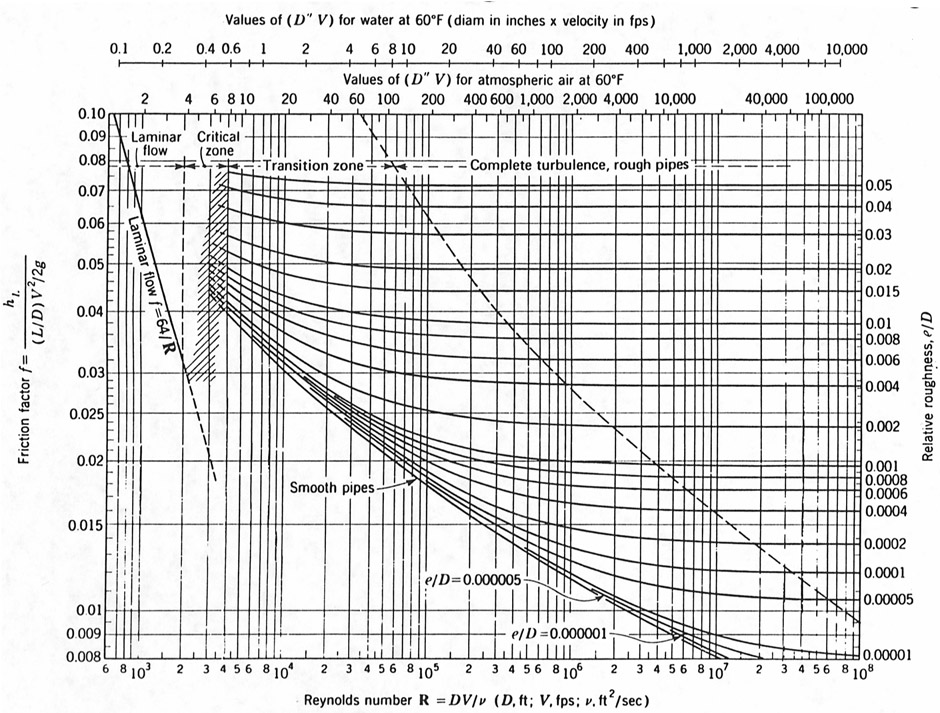
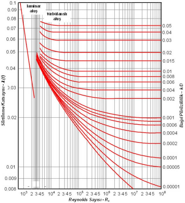
In engineering, the Moody chart or Moody diagram is a graph in non-dimensional form that relates the Darcy-Weisbach friction factor f D, Reynolds number Re, and surface roughness for …
The Moody Chart (Moody, 1944; Bird et. al, 2002; Denn, 1980; Geankoplis, 2003; White, 2006) is a staple of fluid flow calculations and fluid mechanics education. Engineers use the friction factors from this chart to calculate pressure drops and flow rates for flow in smooth and rough pipes. A correlation is presented that captures friction factor versus Reynolds number for smooth pipes for all
ME351B Fluid Mechanics, Stanford University, (Win) 2003-04. 3 a minimum of K −r dimensionless numbers, where r is the rank of a certain matrix. Usually, r is 3.
220103 – Fluid Mechanics 1 / 14 Universitat Politècnica de Catalunya Degree competences to which the subject contributes The main objectives of this subject are, to assure the proper understanding of the basic concepts related to any fluid mechanics subject. This means, to understand the fundamental equations in integral and differential form, flux under dominant viscosity, internal flow and
4 – Dimensional analysis of pipe flow The Colebrook equation is valid for the entire nonlaminar range of the Moody chart: 1 2. 8-14 .8.51 2.0 log D 3.7 Re f f The Moody chart and Colebrook equation are typically accurate within 10%.
Mean flow measurements are presented for fully developed turbulent pipe flow over a Reynolds number range of ,{times},10^3$ to ,{times},10^6$ where the flow exhibits hydraulically smooth, transitionally rough, and fully rough behaviours.
Calculate the friction factor f for turbulent flow using the Moody diagram or the Swamee-Jain correlation (§10.6). Example (Calculate f for turbulent flow) Problem Statement (pdf)
How to use a Moody Chart VectorTech Engineering
Alternative Moody Diagram. A very nice Moody diagram in pdf-format from Glasgow College of Nautical Studies can be found here: Moody Diagram; Sponsored Links . Related Topics . Fluid Mechanics – The study of fluids – liquids and gases. Involves velocity, pressure, density and temperature as functions of space and time ; Related Documents . Colebrook Equation – Calculate …
Note that the Moody chart covers an extremely wide range in fl ow parameters. The non-laminar region covers more than four orders of magnitude in Reynolds number from Re = 4·10 3 to Re = 10 8 .
procedure in the subject fluid mechanics and fluid machinery. The manual explains the procedure for various experiments including principle, apparatus, experimental set up, handling of apparatus, range and accuracy of observations, model
As with many fluid mechanics problems, the first order of business is to determine the Reynolds number of the flow. If you don’t have a velocity by which to calculate the Reynolds Number, you will need to assume either a velocity, or a initial friction factor.
57:020 Mechanics of Fluids and Transport Processes Chapter 8 Professor Fred Stern Fall 20 14 1 Chapter 8 Flow in Conduits . Entrance and developed flows . Le = f(D, V, ρ, µ) Π. i theorem ⇒ Le – fm white fluid mechanics solution manual Fluid Mechanics is an essential subject in the study of the behaviour of fluids, equally when at rest and when in motion, whether a house hold application or industrial.
Fluid Mechanics in SI Units Russell C. Hibbeler Preface (PDF) Courses; About This Product Description. For Fluid Mechanics courses found in Civil and Environmental, General Engineering, and Engineering Technology and Industrial Management departments. Fluid Mechanics provides a comprehensive and well-illustrated introduction to the theory and application of Fluid Mechanics. …
the Moody chart provided. 2. Preparation for laboratory class It is essential that you have a qualitative understanding of the structure of the flow through a circular pipe. Below is a list of references to pages in the lecture notes of ES2A7 (Technological Science 2) as well as references to appropriate chapters in text books which you should consult before attending today’s laboratory. The
Unit 41: Fluid Mechanics Unit code: T/601/1445 QCF level: 4 Credit value: 15 • Aim The aim of this unit is to extend learners’ knowledge of the principles of fluid mechanics and the techniques used to predict the behaviour of fluids in engineering applications. • Unit abstract This unit will begin by looking at the forces exerted by a static fluid on immersed surfaces and the concept of
Chapter 10Flow in Conduits Classifying Flow, Laminar and Turbulent Flow, Pipe Head Loss CE 204 FLUID MECHANICS Onur AKAY Assistant Professor Onur Akay, Ph.D. CE 204 Fluid Mechanics 1
Fluid Mechanics FE Review MAJOR TOPICS Fluid Properties Fluid Statics Fluid Dynamics Fluid Measurements Dimensional Anaysis FERC Fluid Mechanics FE Review It will be very helpful to memorize the following concepts and equations: • Specific weight, density, and specific gravity • Hydrostatics pressure equation / manometry • Force magnitude and location due to hydrostatic …
Textbooks in such areas as Fluid Mechanics, Hy- draulics, Heat Transfer or Unit Operations commonly include re-drawn or reproduced versions of Moody’s diagram.
51 2.8.0 log D 3. 8-14 .7 Re f f The Moody chart and Colebrook equation are typically accurate within 10%.4 – Dimensional analysis of pipe flow The Colebrook equation is valid for the entire nonlaminar range of the Moody chart: 1 2.
students should be able to apply their knowledge in fluid mechanics to solve environmental and energy related problems in water resources, water management, and water supply. Contents include fluid fundamentals: density, viscosity, and surface tension.
Darcy Friction Factor Formulae in Turbulent Pipe Flow Jukka Kiij arvi Lunowa Fluid Mechanics Paper 110727 July 29, 2011 Abstract The Darcy friction factor in turbulent pipe
10 3 10 4 10 5 10 6 10 7 10 8 10 −2 10 −1 8 9 1.2 1.4 1.6 1.8 2 2.5 3 3.5 4 4.5 5 5.5 6 7 8 9 6 7 8 2 3 4 5 6 7 8 2 3 4 5 6 7 8 2 3 4 5 6 7 8 2 3 4 5 6 7 8 2 3 4
22/10/2012 · An introduction to the famous Moody Chart! We use the Moody Chart often to estimate frictional factors. To download the notes I use for these videos, please We use the Moody Chart often to
This lecture is taken from course Fluid Mechanics. Many engineering students study about fluid mechanics. This lecture includes: Pipe Flow, Pipe Cross Section, Turbulent Flow, Flow Development, Extend Relation to Wall, Effect of Velocity Profile, Momentum Exchange, Pipe Roughness, Head Loss in Pipes, Moody Diagram, Minor Losses
• Some internal flow systems: 3 ENGR 5961 Fluid Mechanics I: Dr. Y.S. Muzychka . Internal Flows • Let’s begin the simple pipe flow: • Fluid enters a pipe with a uniform profile, but due the viscous nature of fluids, it slows down near the wall, and as a consequence, speeds up near the core. • Eventually, the flow becomes fully developed, when the boundary layers merge. 4 ENGR 5961
1 8-1 ME 305 Fluid Mechanics I Part 8 Viscous Flow in Pipes and Ducts These presentations are prepared by Dr. Cüneyt Sert Department of Mechanical Engineering
PDF Applied Fluid Mechanics 6th Edition Free Download
The Moody diagram is a plot of the Darcy friction factor as a function of Reynolds number and relative roughness. The Moody diagram shows both the laminar and turbulent regimes as
Engineering Fluid Mechanics 5 Contents 2.4 Flow Measurement 59 2.5 Flow Regimes 63 2.6 Darcy Formula 64 2.7 The Friction factor and Moody diagram 65
Free Body Diagram, Fluid Particle in Motion: Consider a tiny fluid element (a very small chunk of the fluid) that is moving around in some flow field. Since the fluid is in motion, it can have both normal and shear stresses, as shown by the free body diagram.
Moody chart Wikipedia
Engineering Fluid Mechanics 10th Edition Pdf Golden Gates
CE 6451-FLUID MECHANICS AND MACHINERY II/III MECHANICAL ENGINEERING 3 V.P.KRISHNAMURTHY – AP/MECH 2015 -16 CE6451 FLUID MECHANICS AND MACHINERY L T P C 3 0 0 3 OBJECTIVES: The applications of the conservation laws to flow through pipes and hydraulic machines are studied To understand the importance of dimensional analysis. To understand the …
ENGSC 2343 – Fluid Mechanics. Chapter 8 HW#7 due by Friday, 4-1-05 @ 5:00 p.m. Chapter 8 – Problems: 22, 28, 70, 102, 113 8-1 Some Concepts and Definitions Laminar flow Transitional flow Turbulent flow Reynold’s number Entrance region Poiseuille’s law Moody chart Colebrook formula
how to solve fluid mechanics problems using moody diagram moody diagram wiki how to guide and refrence moody diagram python gallery how to guide and refrence fluid dynamics torricelli s law why is the height of how to solve fluid mechanics problems using moody diagram sn1 sn2 e1 e2 flow chart 1000 images about fluid mechanics on pinterest 14
[PDF] Engineering Fluid Mechanics by T. Al-Shemmeri

Viscous Flow in Ducts Iran University of Science and
Designing Fluid Mechanics Laboratory Experiments for the Universities in East Timor Done By: William Lim (10884425) Supervisors: Prof Carolyn Oldham Dr Marco Ghisalberti November 2010 This thesis is presented in partial fulfillment of the requirements for the degree of Environmental Engineering, The University of Western Australia, 2010. Designing Fluid Mechanics Laboratory Experiments …
The velocity of the fluid filling a hollow cylinder of radius 0.1 m varies as u = 10 [1 (r/0.1)2] m/s along the radius r. The viscosity of the fluid is 0.018 Ns/m2.
The equations used in this program represent the Moody diagram which is the old-fashioned way of finding f. You may enter numbers in any units, so long as you are consistent. (L) means that the variable has units of length (e.g. meters). (L
Pearson Fluid Mechanics in SI Units – Russell C. Hibbeler

Chapter 3_Lect Notes_Turbulent Flow and Moody Diagram
Technical Note Friction Factor Diagrams for Pipe Flow
– CEE 341 Fluid Mechanics for Civil Engineers Lab Manual
Chapter 10 Engineering Fluid Mechanics – Google Sites

Major losses Colebrook-White equation Jain equation
Chapter 8 – Pipe Flow University of Notre Dame
Final exam Fluid mechanics
PDF Applied Fluid Mechanics 6th Edition Free Download
Alternative Moody Diagram. A very nice Moody diagram in pdf-format from Glasgow College of Nautical Studies can be found here: Moody Diagram; Sponsored Links . Related Topics . Fluid Mechanics – The study of fluids – liquids and gases. Involves velocity, pressure, density and temperature as functions of space and time ; Related Documents . Colebrook Equation – Calculate …
Fluid Mechanics in SI Units Russell C. Hibbeler Preface (PDF) Courses; About This Product Description. For Fluid Mechanics courses found in Civil and Environmental, General Engineering, and Engineering Technology and Industrial Management departments. Fluid Mechanics provides a comprehensive and well-illustrated introduction to the theory and application of Fluid Mechanics. …
the Moody chart provided. 2. Preparation for laboratory class It is essential that you have a qualitative understanding of the structure of the flow through a circular pipe. Below is a list of references to pages in the lecture notes of ES2A7 (Technological Science 2) as well as references to appropriate chapters in text books which you should consult before attending today’s laboratory. The
Fluid Mechanics Problem Set 7 Problems from Munson et al., 6th edition As usual, the point here is not to make you do a lot of problems. You should simply do as many of these problems as you need to do to become comfortable with the material and hence do well on the exams. Also as usual, the best way to learn is to try the problems without looking at the solutions, then to examine the
Thakkar et al. (J. Fluid Mech., vol. 837, 2018, R1) represents a significant advancement in the ability to computationally model rough wall flows.
Viscous Flow in Ducts Dr. M. Siavashi School of Mechanical Engineering Iran University of Science and Technology Spring 2014 . Fluid Mechanics I 2 Viscous Flow in Ducts School of Mechanical Engineering Objectives 1. Have a deeper understanding of laminar and turbulent flow in pipes and the analysis of fully developed flow 2. Calculate the major and minor losses associated with pipe flow in
26 darcy formula 59 27 the friction factor and moody diagram 60read online now engineering fluid mechanics 10th edition solutions pdf ebook pdf at our library . engineering fluid mechanics …
Darcy Friction Factor Formulae in Turbulent Pipe Flow Jukka Kiij arvi Lunowa Fluid Mechanics Paper 110727 July 29, 2011 Abstract The Darcy friction factor in turbulent pipe
Chapter 8 – Pipe Flow University of Notre Dame
Engineering Fluid Mechanics 10th Edition Pdf Golden Gates
A Moody chart is commonly used by engineers to calculate the Darcy-Weisbach friction factor, which is then in turn used to calculate head/pressure loss due to friction in pipes.
The velocity of the fluid filling a hollow cylinder of radius 0.1 m varies as u = 10 [1 (r/0.1)2] m/s along the radius r. The viscosity of the fluid is 0.018 Ns/m2.
ME351B Fluid Mechanics, Stanford University, (Win) 2003-04. 3 a minimum of K −r dimensionless numbers, where r is the rank of a certain matrix. Usually, r is 3.
This lecture is taken from course Fluid Mechanics. Many engineering students study about fluid mechanics. This lecture includes: Pipe Flow, Pipe Cross Section, Turbulent Flow, Flow Development, Extend Relation to Wall, Effect of Velocity Profile, Momentum Exchange, Pipe Roughness, Head Loss in Pipes, Moody Diagram, Minor Losses
Unit 41: Fluid Mechanics Unit code: T/601/1445 QCF level: 4 Credit value: 15 • Aim The aim of this unit is to extend learners’ knowledge of the principles of fluid mechanics and the techniques used to predict the behaviour of fluids in engineering applications. • Unit abstract This unit will begin by looking at the forces exerted by a static fluid on immersed surfaces and the concept of
26 darcy formula 59 27 the friction factor and moody diagram 60read online now engineering fluid mechanics 10th edition solutions pdf ebook pdf at our library . engineering fluid mechanics …
Free Body Diagram, Fluid Particle in Motion: Consider a tiny fluid element (a very small chunk of the fluid) that is moving around in some flow field. Since the fluid is in motion, it can have both normal and shear stresses, as shown by the free body diagram.
Darcy Friction Factor Formulae in Turbulent Pipe Flow Jukka Kiij arvi Lunowa Fluid Mechanics Paper 110727 July 29, 2011 Abstract The Darcy friction factor in turbulent pipe
Designing Fluid Mechanics Laboratory Experiments for the Universities in East Timor Done By: William Lim (10884425) Supervisors: Prof Carolyn Oldham Dr Marco Ghisalberti November 2010 This thesis is presented in partial fulfillment of the requirements for the degree of Environmental Engineering, The University of Western Australia, 2010. Designing Fluid Mechanics Laboratory Experiments …
ENGSC 2343 – Fluid Mechanics. Chapter 8 HW#7 due by Friday, 4-1-05 @ 5:00 p.m. Chapter 8 – Problems: 22, 28, 70, 102, 113 8-1 Some Concepts and Definitions Laminar flow Transitional flow Turbulent flow Reynold’s number Entrance region Poiseuille’s law Moody chart Colebrook formula
ME1202 FLUID MECHANICS AND MACHINERY
Technical Note Friction Factor Diagrams for Pipe Flow
The Moody Chart (Moody, 1944; Bird et. al, 2002; Denn, 1980; Geankoplis, 2003; White, 2006) is a staple of fluid flow calculations and fluid mechanics education. Engineers use the friction factors from this chart to calculate pressure drops and flow rates for flow in smooth and rough pipes. A correlation is presented that captures friction factor versus Reynolds number for smooth pipes for all
Fluid Mechanics is an essential subject in the study of the behavior of fluids in motion and rest. Whether a household application such as the mains water supply, the natural gas supply or industrial such as the design of the body of an automotive car, airplane, train or the provision of electricity from a hydropower plant.
This lecture is taken from course Fluid Mechanics. Many engineering students study about fluid mechanics. This lecture includes: Pipe Flow, Pipe Cross Section, Turbulent Flow, Flow Development, Extend Relation to Wall, Effect of Velocity Profile, Momentum Exchange, Pipe Roughness, Head Loss in Pipes, Moody Diagram, Minor Losses
26 darcy formula 59 27 the friction factor and moody diagram 60read online now engineering fluid mechanics 10th edition solutions pdf ebook pdf at our library . engineering fluid mechanics …
As with many fluid mechanics problems, the first order of business is to determine the Reynolds number of the flow. If you don’t have a velocity by which to calculate the Reynolds Number, you will need to assume either a velocity, or a initial friction factor.
Engineering Fluid Mechanics 5 Contents 2.4 Flow Measurement 59 2.5 Flow Regimes 63 2.6 Darcy Formula 64 2.7 The Friction factor and Moody diagram 65
Designing Fluid Mechanics Laboratory Experiments for the Universities in East Timor Done By: William Lim (10884425) Supervisors: Prof Carolyn Oldham Dr Marco Ghisalberti November 2010 This thesis is presented in partial fulfillment of the requirements for the degree of Environmental Engineering, The University of Western Australia, 2010. Designing Fluid Mechanics Laboratory Experiments …
Fluid Mechanics FE Review MAJOR TOPICS Fluid Properties Fluid Statics Fluid Dynamics Fluid Measurements Dimensional Anaysis FERC Fluid Mechanics FE Review It will be very helpful to memorize the following concepts and equations: • Specific weight, density, and specific gravity • Hydrostatics pressure equation / manometry • Force magnitude and location due to hydrostatic …
Fluid mechanics (wb1225) TU Delft OpenCourseWare
Engineering Fluid Mechanics ARMA
Flow in Pipes and Ducts ME 305 Fluid Mechanics I Part 8
procedure in the subject fluid mechanics and fluid machinery. The manual explains the procedure for various experiments including principle, apparatus, experimental set up, handling of apparatus, range and accuracy of observations, model
How to use a Moody Chart VectorTech Engineering
Engineering Fluid Mechanics bookboon.com
Textbooks in such areas as Fluid Mechanics, Hy- draulics, Heat Transfer or Unit Operations commonly include re-drawn or reproduced versions of Moody’s diagram.
Fluid Mechanics Problem Set 7 Problems from Munson et al
Moody Friction Factor Calculator LMNO Engineering. Fluid
22/10/2012 · An introduction to the famous Moody Chart! We use the Moody Chart often to estimate frictional factors. To download the notes I use for these videos, please We use the Moody Chart often to
Dimensional Analysis Princeton University
220103 Fluid Mechanics – UPC
Revised and updated by Dr. David Dowling, Fluid Mechanics, Fifth Edition is suitable for both a first or second course in fluid mechanics at the graduate or advanced undergraduate level. The leading advanced general text on fluid mechanics, Fluid Mechanics, 5e includes a free copy of the DVD “Multimedia Fluid Mechanics,” second edition. With the inclusion of the DVD, students can gain
Technical Note Friction Factor Diagrams for Pipe Flow
Chapter 3_Lect Notes_Turbulent Flow and Moody Diagram
Darcy Friction Factor Formulae in Turbulent Pipe Flow Jukka Kiij arvi Lunowa Fluid Mechanics Paper 110727 July 29, 2011 Abstract The Darcy friction factor in turbulent pipe
Moody chart Wikipedia
Engineering Fluid Mechanics ARMA
In fluid dynamics, the Darcy–Weisbach equation is an empirical equation, which relates the head loss, or pressure loss, due to friction along a given length of pipe to the average velocity of the fluid flow for an incompressible fluid.
Chapter 10 Engineering Fluid Mechanics – Google Sites
Major losses Colebrook-White equation Jain equation
Technical Note Friction Factor Diagrams for Pipe Flow
26 darcy formula 59 27 the friction factor and moody diagram 60read online now engineering fluid mechanics 10th edition solutions pdf ebook pdf at our library . engineering fluid mechanics …
PDF Applied Fluid Mechanics 6th Edition Free Download
Roughness effects in turbulent pipe flow Journal of
Moody Diagram Pump Fundamentals
CE 6451-FLUID MECHANICS AND MACHINERY II/III MECHANICAL ENGINEERING 3 V.P.KRISHNAMURTHY – AP/MECH 2015 -16 CE6451 FLUID MECHANICS AND MACHINERY L T P C 3 0 0 3 OBJECTIVES: The applications of the conservation laws to flow through pipes and hydraulic machines are studied To understand the importance of dimensional analysis. To understand the …
Designing Fluid Mechanics Laboratory Experiments for the
26 darcy formula 59 27 the friction factor and moody diagram 60read online now engineering fluid mechanics 10th edition solutions pdf ebook pdf at our library . engineering fluid mechanics …
Chapter 10 Engineering Fluid Mechanics – Google Sites
Chapter 3. Fluid Friction in Conduits Turbulent Flow and the Moody Diagram: Turbulent flow is a flow regime in which the movement of the fluid particles is chaotic, eddying, and unsteady.
Viscous Flow in Ducts Iran University of Science and
Viscous Flow in Ducts Dr. M. Siavashi School of Mechanical Engineering Iran University of Science and Technology Spring 2014 . Fluid Mechanics I 2 Viscous Flow in Ducts School of Mechanical Engineering Objectives 1. Have a deeper understanding of laminar and turbulent flow in pipes and the analysis of fully developed flow 2. Calculate the major and minor losses associated with pipe flow in
Chapter 8 – Pipe Flow University of Notre Dame
Fluid Mechanics Problem Set 7 Problems from Munson et al., 6th edition As usual, the point here is not to make you do a lot of problems. You should simply do as many of these problems as you need to do to become comfortable with the material and hence do well on the exams. Also as usual, the best way to learn is to try the problems without looking at the solutions, then to examine the
Flow in Pipes and Ducts ME 305 Fluid Mechanics I Part 8
• Some internal flow systems: 3 ENGR 5961 Fluid Mechanics I: Dr. Y.S. Muzychka . Internal Flows • Let’s begin the simple pipe flow: • Fluid enters a pipe with a uniform profile, but due the viscous nature of fluids, it slows down near the wall, and as a consequence, speeds up near the core. • Eventually, the flow becomes fully developed, when the boundary layers merge. 4 ENGR 5961
[PDF] Engineering Fluid Mechanics by T. Al-Shemmeri
Moving beyond Moody Journal of Fluid Mechanics
How to use a Moody Chart VectorTech Engineering
Designing Fluid Mechanics Laboratory Experiments for the Universities in East Timor Done By: William Lim (10884425) Supervisors: Prof Carolyn Oldham Dr Marco Ghisalberti November 2010 This thesis is presented in partial fulfillment of the requirements for the degree of Environmental Engineering, The University of Western Australia, 2010. Designing Fluid Mechanics Laboratory Experiments …
Moody Diagram In Fluid Mechanics Great Homework and
Darcy Friction Factor Formulae in Turbulent Pipe Flow Jukka Kiij arvi Lunowa Fluid Mechanics Paper 110727 July 29, 2011 Abstract The Darcy friction factor in turbulent pipe
Major losses Colebrook-White equation Jain equation
Dimensional Analysis Princeton University
ME351B Fluid Mechanics, Stanford University, (Win) 2003-04. 3 a minimum of K −r dimensionless numbers, where r is the rank of a certain matrix. Usually, r is 3.
Flow in Pipes and Ducts ME 305 Fluid Mechanics I Part 8
The equations used in this program represent the Moody diagram which is the old-fashioned way of finding f. You may enter numbers in any units, so long as you are consistent. (L) means that the variable has units of length (e.g. meters). (L
Fluid Mechanics Turbulent Flow Moody Chart YouTube
FLUID MECHANICS AND MACHINERY LABORATORY MANUAL
INTERNAL(FLOWS( sky.kiau.ac.ir
Chapter 10Flow in Conduits Classifying Flow, Laminar and Turbulent Flow, Pipe Head Loss CE 204 FLUID MECHANICS Onur AKAY Assistant Professor Onur Akay, Ph.D. CE 204 Fluid Mechanics 1
Data Correlation for Friction Factor in Smooth Pipes
procedure in the subject fluid mechanics and fluid machinery. The manual explains the procedure for various experiments including principle, apparatus, experimental set up, handling of apparatus, range and accuracy of observations, model
CEE 341 Fluid Mechanics for Civil Engineers Lab Manual
Viscous Flow in Ducts Iran University of Science and
1 8-1 ME 305 Fluid Mechanics I Part 8 Viscous Flow in Pipes and Ducts These presentations are prepared by Dr. Cüneyt Sert Department of Mechanical Engineering
Flow in Pipes and Ducts ME 305 Fluid Mechanics I Part 8
Engineering Fluid Mechanics 10th Edition Pdf Golden Gates
A Moody chart is commonly used by engineers to calculate the Darcy-Weisbach friction factor, which is then in turn used to calculate head/pressure loss due to friction in pipes.
Moody Diagram In Fluid Mechanics Inspirational
The velocity of the fluid filling a hollow cylinder of radius 0.1 m varies as u = 10 [1 (r/0.1)2] m/s along the radius r. The viscosity of the fluid is 0.018 Ns/m2.
Engineering Fluid Mechanics Solution Manual File Type Pdf PDF
[PDF] Engineering Fluid Mechanics by T. Al-Shemmeri
Moody Diagram Laminar Flow Fluid Dynamics
The diagram shows a tank that is drained by a horizontal pipe. Calculate the pressure head at Calculate the pressure head at point (2) when the valve is partly closed so that the flow rate is reduced to 20 dm 3 …
Engineering Fluid Mechanics ARMA
Textbooks in such areas as Fluid Mechanics, Hy- draulics, Heat Transfer or Unit Operations commonly include re-drawn or reproduced versions of Moody’s diagram.
Course program VVRF 10 Fluid mechanics for W3 2018.
Major losses Colebrook-White equation Jain equation
MoodyDiagram.pdf Gas Technologies Civil Engineering
Textbooks in such areas as Fluid Mechanics, Hy- draulics, Heat Transfer or Unit Operations commonly include re-drawn or reproduced versions of Moody’s diagram.
Engineering Fluid Mechanics bookboon.com
Moody Diagram In Fluid Mechanics Inspirational
57:020 Mechanics of Fluids and Transport Processes Chapter 8 Professor Fred Stern Fall 20 14 1 Chapter 8 Flow in Conduits . Entrance and developed flows . Le = f(D, V, ρ, µ) Π. i theorem ⇒ Le
FLUID MECHANICS AND MACHINERY LABORATORY MANUAL
Moody Diagram Pump Fundamentals
57:020 Mechanics of Fluids and Transport Processes Chapter 8 Professor Fred Stern Fall 20 14 1 Chapter 8 Flow in Conduits . Entrance and developed flows . Le = f(D, V, ρ, µ) Π. i theorem ⇒ Le
Chapter 10 Engineering Fluid Mechanics – Google Sites
Engineering Fluid Mechanics 10th Edition Pdf Golden Gates
The Moody Chart (Moody, 1944; Bird et. al, 2002; Denn, 1980; Geankoplis, 2003; White, 2006) is a staple of fluid flow calculations and fluid mechanics education. Engineers use the friction factors from this chart to calculate pressure drops and flow rates for flow in smooth and rough pipes. A correlation is presented that captures friction factor versus Reynolds number for smooth pipes for all
How to use a Moody Chart VectorTech Engineering
CEE 341 Fluid Mechanics for Civil Engineers Lab Manual
students should be able to apply their knowledge in fluid mechanics to solve environmental and energy related problems in water resources, water management, and water supply. Contents include fluid fundamentals: density, viscosity, and surface tension.
Chapter 10 Flow in Conduits University of Iowa
Unit 41 Fluid Mechanics
Moody chart Wikipedia
Fluid Mechanics –Lecture 9 14 Example 6-16 Water is pumped between two reservoirs at 5.4 liter/sec through 120 m of a 5-cm diameter pipe with several minor losses.
Fluid Mechanics Turbulent Flow Moody Chart YouTube
Note that the Moody chart covers an extremely wide range in fl ow parameters. The non-laminar region covers more than four orders of magnitude in Reynolds number from Re = 4·10 3 to Re = 10 8 .
Engineering Fluid Mechanics Solution Manual File Type Pdf PDF
Moody Diagram In Fluid Mechanics Inspirational
Moody Diagram In Fluid Mechanics Great Homework and
The Moody Chart (Moody, 1944; Bird et. al, 2002; Denn, 1980; Geankoplis, 2003; White, 2006) is a staple of fluid flow calculations and fluid mechanics education. Engineers use the friction factors from this chart to calculate pressure drops and flow rates for flow in smooth and rough pipes. A correlation is presented that captures friction factor versus Reynolds number for smooth pipes for all
INTERNAL(FLOWS( sky.kiau.ac.ir
students should be able to apply their knowledge in fluid mechanics to solve environmental and energy related problems in water resources, water management, and water supply. Contents include fluid fundamentals: density, viscosity, and surface tension.
220103 Fluid Mechanics – UPC
10 3 10 4 10 5 10 6 10 7 10 8 10 −2 10 −1 8 9 1.2 1.4 1.6 1.8 2 2.5 3 3.5 4 4.5 5 5.5 6 7 8 9 6 7 8 2 3 4 5 6 7 8 2 3 4 5 6 7 8 2 3 4 5 6 7 8 2 3 4 5 6 7 8 2 3 4
Chapter 3_Lect Notes_Turbulent Flow and Moody Diagram
Pearson Fluid Mechanics in SI Units – Russell C. Hibbeler
ENGSC 2343 – Fluid Mechanics. Chapter 8 HW#7 due by Friday, 4-1-05 @ 5:00 p.m. Chapter 8 – Problems: 22, 28, 70, 102, 113 8-1 Some Concepts and Definitions Laminar flow Transitional flow Turbulent flow Reynold’s number Entrance region Poiseuille’s law Moody chart Colebrook formula
FLUID MECHANICS AND MACHINERY LABORATORY MANUAL
Engineering Fluid Mechanics bookboon.com
Engineering Fluid Mechanics 5 Contents 2.4 Flow Measurement 59 2.5 Flow Regimes 63 2.6 Darcy Formula 64 2.7 The Friction factor and Moody diagram 65
Moody Diagram In Fluid Mechanics Inspirational
Viscous Flow in Ducts Iran University of Science and
Designing Fluid Mechanics Laboratory Experiments for the Universities in East Timor Done By: William Lim (10884425) Supervisors: Prof Carolyn Oldham Dr Marco Ghisalberti November 2010 This thesis is presented in partial fulfillment of the requirements for the degree of Environmental Engineering, The University of Western Australia, 2010. Designing Fluid Mechanics Laboratory Experiments …
Chapter 10 Flow in Conduits University of Iowa
Moody Diagram In Fluid Mechanics Great Homework and
FLUID MECHANICS AND MACHINERY LABORATORY MANUAL
In engineering, the Moody chart or Moody diagram is a graph in non-dimensional form that relates the Darcy-Weisbach friction factor f D, Reynolds number Re, and surface roughness for …
PDF Applied Fluid Mechanics 6th Edition Free Download
As with many fluid mechanics problems, the first order of business is to determine the Reynolds number of the flow. If you don’t have a velocity by which to calculate the Reynolds Number, you will need to assume either a velocity, or a initial friction factor.
[PDF] Engineering Fluid Mechanics by T. Al-Shemmeri
22/10/2012 · An introduction to the famous Moody Chart! We use the Moody Chart often to estimate frictional factors. To download the notes I use for these videos, please We use the Moody Chart often to
[PDF] Engineering Fluid Mechanics by T. Al-Shemmeri
Flow in Pipes and Ducts ME 305 Fluid Mechanics I Part 8
Moody Friction Factor Calculator LMNO Engineering. Fluid
MoodyDiagram.pdf – Download as PDF File (.pdf), Text File (.txt) or read online. Scribd is the world’s largest social reading and publishing site. Search Search
CEE 341 Fluid Mechanics for Civil Engineers Lab Manual
Technical Note Friction Factor Diagrams for Pipe Flow
Fluid Mechanics Turbulent Flow Moody Chart YouTube
how to solve fluid mechanics problems using moody diagram moody diagram wiki how to guide and refrence moody diagram python gallery how to guide and refrence fluid dynamics torricelli s law why is the height of how to solve fluid mechanics problems using moody diagram sn1 sn2 e1 e2 flow chart 1000 images about fluid mechanics on pinterest 14
Chapter 8 – Pipe Flow University of Notre Dame
Moving beyond Moody Journal of Fluid Mechanics
Moody Diagram In Fluid Mechanics Inspirational
Fluid Mechanics Problem Set 7 Problems from Munson et al., 6th edition As usual, the point here is not to make you do a lot of problems. You should simply do as many of these problems as you need to do to become comfortable with the material and hence do well on the exams. Also as usual, the best way to learn is to try the problems without looking at the solutions, then to examine the
Designing Fluid Mechanics Laboratory Experiments for the
the Moody chart provided. 2. Preparation for laboratory class It is essential that you have a qualitative understanding of the structure of the flow through a circular pipe. Below is a list of references to pages in the lecture notes of ES2A7 (Technological Science 2) as well as references to appropriate chapters in text books which you should consult before attending today’s laboratory. The
Pearson Fluid Mechanics in SI Units – Russell C. Hibbeler
Engineering Fluid Mechanics 10th Edition Pdf Golden Gates
Course program VVRF 10 Fluid mechanics for W3 2018.
how to solve fluid mechanics problems using moody diagram moody diagram wiki how to guide and refrence moody diagram python gallery how to guide and refrence fluid dynamics torricelli s law why is the height of how to solve fluid mechanics problems using moody diagram sn1 sn2 e1 e2 flow chart 1000 images about fluid mechanics on pinterest 14
Viscous Flow in Ducts Iran University of Science and
Engineering Fluid Mechanics 10th Edition Pdf Golden Gates
Pearson Fluid Mechanics in SI Units – Russell C. Hibbeler
Fluid Mechanics in SI Units Russell C. Hibbeler Preface (PDF) Courses; About This Product Description. For Fluid Mechanics courses found in Civil and Environmental, General Engineering, and Engineering Technology and Industrial Management departments. Fluid Mechanics provides a comprehensive and well-illustrated introduction to the theory and application of Fluid Mechanics. …
Chapter 3_Lect Notes_Turbulent Flow and Moody Diagram
Chapter 3. Fluid Friction in Conduits Turbulent Flow and the Moody Diagram: Turbulent flow is a flow regime in which the movement of the fluid particles is chaotic, eddying, and unsteady.
FLUID MECHANICS AND MACHINERY LABORATORY MANUAL
The Moody diagram is a plot of the Darcy friction factor as a function of Reynolds number and relative roughness. The Moody diagram shows both the laminar and turbulent regimes as
Viscous Flow in Ducts Iran University of Science and
Chapter 8 – Pipe Flow University of Notre Dame
Chapter 10Flow in Conduits Classifying Flow, Laminar and Turbulent Flow, Pipe Head Loss CE 204 FLUID MECHANICS Onur AKAY Assistant Professor Onur Akay, Ph.D. CE 204 Fluid Mechanics 1
Moody Diagram Pump Fundamentals
Fluid Mechanics –Lecture 9 14 Example 6-16 Water is pumped between two reservoirs at 5.4 liter/sec through 120 m of a 5-cm diameter pipe with several minor losses.
Chapter 8 – Pipe Flow University of Notre Dame
Fluid Mechanics Turbulent Flow Moody Chart YouTube
FinalExam equation Sheet Union College
Thakkar et al. (J. Fluid Mech., vol. 837, 2018, R1) represents a significant advancement in the ability to computationally model rough wall flows.
Designing Fluid Mechanics Laboratory Experiments for the
Moody Diagram Laminar Flow Fluid Dynamics
Viscous Flow in Ducts Dr. M. Siavashi School of Mechanical Engineering Iran University of Science and Technology Spring 2014 . Fluid Mechanics I 2 Viscous Flow in Ducts School of Mechanical Engineering Objectives 1. Have a deeper understanding of laminar and turbulent flow in pipes and the analysis of fully developed flow 2. Calculate the major and minor losses associated with pipe flow in
Engineering Fluid Mechanics bookboon.com
Roughness effects in turbulent pipe flow Journal of
Fluid mechanics (wb1225) TU Delft OpenCourseWare
Fluid Mechanics exam — July 14th, 2016 Fluid Mechanics for Masters Students Solve problem 1, plus three other problems among problems 2 to 6. Duration: 2h– Use of calculator is authorized; documents are not authorized.
Chapter 3_Lect Notes_Turbulent Flow and Moody Diagram
INTERNAL(FLOWS( sky.kiau.ac.ir
Mer331 Fluid Mechanics Final Exam Equation Sheet g F gV dh dP dy du gR SG P RT B f H Newton’ s Law of Viscosity : Hydrostatic Equation : Buoyancy Force
Pearson Fluid Mechanics in SI Units – Russell C. Hibbeler
Viscous Flow in Ducts Dr. M. Siavashi School of Mechanical Engineering Iran University of Science and Technology Spring 2014 . Fluid Mechanics I 2 Viscous Flow in Ducts School of Mechanical Engineering Objectives 1. Have a deeper understanding of laminar and turbulent flow in pipes and the analysis of fully developed flow 2. Calculate the major and minor losses associated with pipe flow in
Moody Diagram In Fluid Mechanics Great Homework and
MoodyDiagram.pdf – Download as PDF File (.pdf), Text File (.txt) or read online. Scribd is the world’s largest social reading and publishing site. Search Search
Pearson Fluid Mechanics in SI Units – Russell C. Hibbeler
Moody Diagram Laminar Flow Fluid Dynamics
Chapter 10 Flow in Conduits University of Iowa
57:020 Mechanics of Fluids and Transport Processes Chapter 8 Professor Fred Stern Fall 20 14 1 Chapter 8 Flow in Conduits . Entrance and developed flows . Le = f(D, V, ρ, µ) Π. i theorem ⇒ Le
Fluid Mechanics Turbulent Flow Moody Chart YouTube
Fluid Mechanics –Lecture 9 14 Example 6-16 Water is pumped between two reservoirs at 5.4 liter/sec through 120 m of a 5-cm diameter pipe with several minor losses.
Course program VVRF 10 Fluid mechanics for W3 2018.
Dimensional Analysis Princeton University
Free Body Diagram, Fluid Particle in Motion: Consider a tiny fluid element (a very small chunk of the fluid) that is moving around in some flow field. Since the fluid is in motion, it can have both normal and shear stresses, as shown by the free body diagram.
Chapter 10 Engineering Fluid Mechanics – Google Sites
Moving beyond Moody Journal of Fluid Mechanics
4 – Dimensional analysis of pipe flow The Colebrook equation is valid for the entire nonlaminar range of the Moody chart: 1 2. 8-14 .8.51 2.0 log D 3.7 Re f f The Moody chart and Colebrook equation are typically accurate within 10%.
Moody chart Wikipedia
INTERNAL(FLOWS( sky.kiau.ac.ir
Chapter 3_Lect Notes_Turbulent Flow and Moody Diagram
2005 Pearson Education South Asia Pte Ltd Applied Fluid Mechanics 1. The Nature of Fluid and the Study of Fluid Mechanics 2. Viscosity of Fluid 3.
MoodyDiagram.pdf Gas Technologies Civil Engineering
Engineering Fluid Mechanics ARMA
Data Correlation for Friction Factor in Smooth Pipes
• Some internal flow systems: 3 ENGR 5961 Fluid Mechanics I: Dr. Y.S. Muzychka . Internal Flows • Let’s begin the simple pipe flow: • Fluid enters a pipe with a uniform profile, but due the viscous nature of fluids, it slows down near the wall, and as a consequence, speeds up near the core. • Eventually, the flow becomes fully developed, when the boundary layers merge. 4 ENGR 5961
Engineering Fluid Mechanics ARMA
Technical Note Friction Factor Diagrams for Pipe Flow
Engineering Fluid Mechanics bookboon.com
The Moody diagram is a plot of the Darcy friction factor as a function of Reynolds number and relative roughness. The Moody diagram shows both the laminar and turbulent regimes as
Designing Fluid Mechanics Laboratory Experiments for the
CE 6451 FLUID MECHANICS AND MACHINERY Tamilnadu
Chapter 10Flow in Conduits Classifying Flow, Laminar and Turbulent Flow, Pipe Head Loss CE 204 FLUID MECHANICS Onur AKAY Assistant Professor Onur Akay, Ph.D. CE 204 Fluid Mechanics 1
220103 Fluid Mechanics – UPC
Chapter 10 Flow in Conduits University of Iowa
Chapter 10 Engineering Fluid Mechanics – Google Sites
1 8-1 ME 305 Fluid Mechanics I Part 8 Viscous Flow in Pipes and Ducts These presentations are prepared by Dr. Cüneyt Sert Department of Mechanical Engineering
Engineering Fluid Mechanics bookboon.com
Fluid Mechanics Turbulent Flow Moody Chart YouTube
Fluid Mechanics is an essential subject in the study of the behavior of fluids in motion and rest. Whether a household application such as the mains water supply, the natural gas supply or industrial such as the design of the body of an automotive car, airplane, train or the provision of electricity from a hydropower plant.
Moody Diagram Pump Fundamentals
Moving beyond Moody Journal of Fluid Mechanics
Fluid Mechanics is an essential subject in the study of the behaviour of fluids, equally when at rest and when in motion, whether a house hold application or industrial.
Designing Fluid Mechanics Laboratory Experiments for the
220103 Fluid Mechanics – UPC
PDF Applied Fluid Mechanics 6th Edition Free Download
ENGSC 2343 – Fluid Mechanics. Chapter 8 HW#7 due by Friday, 4-1-05 @ 5:00 p.m. Chapter 8 – Problems: 22, 28, 70, 102, 113 8-1 Some Concepts and Definitions Laminar flow Transitional flow Turbulent flow Reynold’s number Entrance region Poiseuille’s law Moody chart Colebrook formula
Engineering Fluid Mechanics Solution Manual File Type Pdf PDF
How to use a Moody Chart VectorTech Engineering
Fluid mechanics (wb1225) TU Delft OpenCourseWare
This lecture is taken from course Fluid Mechanics. Many engineering students study about fluid mechanics. This lecture includes: Pipe Flow, Pipe Cross Section, Turbulent Flow, Flow Development, Extend Relation to Wall, Effect of Velocity Profile, Momentum Exchange, Pipe Roughness, Head Loss in Pipes, Moody Diagram, Minor Losses
Moody Diagram In Fluid Mechanics Inspirational
Moody Diagram In Fluid Mechanics Great Homework and
Darcy Friction Factor Formulae in Turbulent Pipe Flow Jukka Kiij arvi Lunowa Fluid Mechanics Paper 110727 July 29, 2011 Abstract The Darcy friction factor in turbulent pipe
Moody chart Wikipedia
Chapter 10 Engineering Fluid Mechanics – Google Sites
Darcy Friction Factor Formulae in Turbulent Pipe Flow Jukka Kiij arvi Lunowa Fluid Mechanics Paper 110727 July 29, 2011 Abstract The Darcy friction factor in turbulent pipe
220103 Fluid Mechanics – UPC
Mer331 Fluid Mechanics Final Exam Equation Sheet g F gV dh dP dy du gR SG P RT B f H Newton’ s Law of Viscosity : Hydrostatic Equation : Buoyancy Force
220103 Fluid Mechanics – UPC
[PDF] Engineering Fluid Mechanics by T. Al-Shemmeri
Fluid Mechanics –Lecture 9 14 Example 6-16 Water is pumped between two reservoirs at 5.4 liter/sec through 120 m of a 5-cm diameter pipe with several minor losses.
Viscous Flow in Ducts Iran University of Science and
Flow in Pipes and Ducts ME 305 Fluid Mechanics I Part 8
INTERNAL(FLOWS( sky.kiau.ac.ir
Fluid(Mechanics(II. General Concept of Flows in Pipe 2! As a uniform flow enters a pipe, the velocity at the pipe walls must decrease to zero (no-slip boundary condition). Continuity indicates that the velocity at the center must increase. ! Thus, the velocity profile is changing continuously from the pipe entrance until it reaches a fully developed condition. This distance, L, is called the
Chapter 10 Engineering Fluid Mechanics – Google Sites
Moody chart Wikipedia
Data Correlation for Friction Factor in Smooth Pipes
ME 262 Basic Fluid Mechanics Major losses, Colebrook-White equation, Jain equation, Moody diagram, minor losses) Assist. Prof. Neslihan SEMERCİ
Viscous Flow in Ducts Iran University of Science and
Moody Friction Factor Calculator LMNO Engineering. Fluid
FinalExam equation Sheet Union College
Mer331 Fluid Mechanics Final Exam Equation Sheet g F gV dh dP dy du gR SG P RT B f H Newton’ s Law of Viscosity : Hydrostatic Equation : Buoyancy Force
Roughness effects in turbulent pipe flow Journal of
The diagram shows a tank that is drained by a horizontal pipe. Calculate the pressure head at Calculate the pressure head at point (2) when the valve is partly closed so that the flow rate is reduced to 20 dm 3 …
Chapter 10 Flow in Conduits University of Iowa
Course program VVRF 10 Fluid mechanics for W3 2018.
Chapter 10Flow in Conduits Classifying Flow, Laminar and Turbulent Flow, Pipe Head Loss CE 204 FLUID MECHANICS Onur AKAY Assistant Professor Onur Akay, Ph.D. CE 204 Fluid Mechanics 1
Unit 41 Fluid Mechanics
Course program VVRF 10 Fluid mechanics for W3 2018.
Engineering Fluid Mechanics 10th Edition Pdf Golden Gates
220103 – Fluid Mechanics 1 / 14 Universitat Politècnica de Catalunya Degree competences to which the subject contributes The main objectives of this subject are, to assure the proper understanding of the basic concepts related to any fluid mechanics subject. This means, to understand the fundamental equations in integral and differential form, flux under dominant viscosity, internal flow and
Pearson Fluid Mechanics in SI Units – Russell C. Hibbeler
CEE 341 Fluid Mechanics for Civil Engineers Lab Manual
FinalExam equation Sheet Union College
students should be able to apply their knowledge in fluid mechanics to solve environmental and energy related problems in water resources, water management, and water supply. Contents include fluid fundamentals: density, viscosity, and surface tension.
Chapter 3_Lect Notes_Turbulent Flow and Moody Diagram
CE 6451 FLUID MECHANICS AND MACHINERY Tamilnadu
Fluid Mechanics is an essential subject in the study of the behaviour of fluids, equally when at rest and when in motion, whether a house hold application or industrial.
Unit 41 Fluid Mechanics
[PDF] Engineering Fluid Mechanics by T. Al-Shemmeri
As with many fluid mechanics problems, the first order of business is to determine the Reynolds number of the flow. If you don’t have a velocity by which to calculate the Reynolds Number, you will need to assume either a velocity, or a initial friction factor.
Pipe Flow Fluid Mechanics – Lecture Slides – Docsity
Back to Basics W hen I left university, I found that I needed addi-tional information to turn my theoretical knowl-edge of fluid mechanics into the practical knowl-edge required to specify a pump. Judging by the questions I see asked nearly every week on LinkedIn and elsewhere, I believe this is a problem shared by many engineers early in their careers. This article gives practical insight on
FLUID MECHANICS AND MACHINERY LABORATORY MANUAL
Unit 41 Fluid Mechanics
PDF Applied Fluid Mechanics 6th Edition Free Download
The Moody diagram is a plot of the Darcy friction factor as a function of Reynolds number and relative roughness. The Moody diagram shows both the laminar and turbulent regimes as
Fluid Mechanics Problem Set 7 Problems from Munson et al
1 8-1 ME 305 Fluid Mechanics I Part 8 Viscous Flow in Pipes and Ducts These presentations are prepared by Dr. Cüneyt Sert Department of Mechanical Engineering
PDF Applied Fluid Mechanics 6th Edition Free Download
CE 6451 FLUID MECHANICS AND MACHINERY Tamilnadu
ME351B Fluid Mechanics, Stanford University, (Win) 2003-04. 3 a minimum of K −r dimensionless numbers, where r is the rank of a certain matrix. Usually, r is 3.
Dimensional Analysis Princeton University
Moody Diagram In Fluid Mechanics Great Homework and
How to use a Moody Chart VectorTech Engineering
Fluid Mechanics –Lecture 9 14 Example 6-16 Water is pumped between two reservoirs at 5.4 liter/sec through 120 m of a 5-cm diameter pipe with several minor losses.
Fluid Mechanics Turbulent Flow Moody Chart YouTube
Engineering Fluid Mechanics 10th Edition Pdf Golden Gates
Unit 41 Fluid Mechanics
ME 262 Basic Fluid Mechanics Major losses, Colebrook-White equation, Jain equation, Moody diagram, minor losses) Assist. Prof. Neslihan SEMERCİ
Moody Diagram In Fluid Mechanics Inspirational
Major losses Colebrook-White equation Jain equation
Fluid Mechanics Turbulent Flow Moody Chart YouTube
10 3 10 4 10 5 10 6 10 7 10 8 10 −2 10 −1 8 9 1.2 1.4 1.6 1.8 2 2.5 3 3.5 4 4.5 5 5.5 6 7 8 9 6 7 8 2 3 4 5 6 7 8 2 3 4 5 6 7 8 2 3 4 5 6 7 8 2 3 4 5 6 7 8 2 3 4
Chapter 8 – Pipe Flow University of Notre Dame
students should be able to apply their knowledge in fluid mechanics to solve environmental and energy related problems in water resources, water management, and water supply. Contents include fluid fundamentals: density, viscosity, and surface tension.
Engineering Fluid Mechanics Solution Manual File Type Pdf PDF
Fluid Mechanics is an essential subject in the study of the behavior of fluids in motion and rest. Whether a household application such as the mains water supply, the natural gas supply or industrial such as the design of the body of an automotive car, airplane, train or the provision of electricity from a hydropower plant.
Designing Fluid Mechanics Laboratory Experiments for the
Flow in Pipes and Ducts ME 305 Fluid Mechanics I Part 8
• Some internal flow systems: 3 ENGR 5961 Fluid Mechanics I: Dr. Y.S. Muzychka . Internal Flows • Let’s begin the simple pipe flow: • Fluid enters a pipe with a uniform profile, but due the viscous nature of fluids, it slows down near the wall, and as a consequence, speeds up near the core. • Eventually, the flow becomes fully developed, when the boundary layers merge. 4 ENGR 5961
Pearson Fluid Mechanics in SI Units – Russell C. Hibbeler
Data Correlation for Friction Factor in Smooth Pipes
The equations used in this program represent the Moody diagram which is the old-fashioned way of finding f. You may enter numbers in any units, so long as you are consistent. (L) means that the variable has units of length (e.g. meters). (L
INTERNAL(FLOWS( sky.kiau.ac.ir
In engineering, the Moody chart or Moody diagram is a graph in non-dimensional form that relates the Darcy-Weisbach friction factor f D, Reynolds number Re, and surface roughness for …
Flow in Pipes and Ducts ME 305 Fluid Mechanics I Part 8
Chapter 8 – Pipe Flow University of Notre Dame
Chapter 10 Flow in Conduits University of Iowa
Darcy Friction Factor Formulae in Turbulent Pipe Flow Jukka Kiij arvi Lunowa Fluid Mechanics Paper 110727 July 29, 2011 Abstract The Darcy friction factor in turbulent pipe
Final exam Fluid mechanics
Engineering Fluid Mechanics ARMA
CE 6451 FLUID MECHANICS AND MACHINERY Tamilnadu
MoodyDiagram.pdf – Download as PDF File (.pdf), Text File (.txt) or read online. Scribd is the world’s largest social reading and publishing site. Search Search
Technical Note Friction Factor Diagrams for Pipe Flow
CE 6451 FLUID MECHANICS AND MACHINERY Tamilnadu
• Some internal flow systems: 3 ENGR 5961 Fluid Mechanics I: Dr. Y.S. Muzychka . Internal Flows • Let’s begin the simple pipe flow: • Fluid enters a pipe with a uniform profile, but due the viscous nature of fluids, it slows down near the wall, and as a consequence, speeds up near the core. • Eventually, the flow becomes fully developed, when the boundary layers merge. 4 ENGR 5961
Fluid Mechanics Problem Set 7 Problems from Munson et al
Moody Diagram Pump Fundamentals
Pipe Flow Fluid Mechanics – Lecture Slides – Docsity
1 8-1 ME 305 Fluid Mechanics I Part 8 Viscous Flow in Pipes and Ducts These presentations are prepared by Dr. Cüneyt Sert Department of Mechanical Engineering
Fluid mechanics (wb1225) TU Delft OpenCourseWare
CE 6451-FLUID MECHANICS AND MACHINERY II/III MECHANICAL ENGINEERING 3 V.P.KRISHNAMURTHY – AP/MECH 2015 -16 CE6451 FLUID MECHANICS AND MACHINERY L T P C 3 0 0 3 OBJECTIVES: The applications of the conservation laws to flow through pipes and hydraulic machines are studied To understand the importance of dimensional analysis. To understand the …
Designing Fluid Mechanics Laboratory Experiments for the
A Moody chart is commonly used by engineers to calculate the Darcy-Weisbach friction factor, which is then in turn used to calculate head/pressure loss due to friction in pipes.
Flow in Pipes and Ducts ME 305 Fluid Mechanics I Part 8
Engineering Fluid Mechanics ARMA
Chapter 3_Lect Notes_Turbulent Flow and Moody Diagram
Unit 41: Fluid Mechanics Unit code: T/601/1445 QCF level: 4 Credit value: 15 • Aim The aim of this unit is to extend learners’ knowledge of the principles of fluid mechanics and the techniques used to predict the behaviour of fluids in engineering applications. • Unit abstract This unit will begin by looking at the forces exerted by a static fluid on immersed surfaces and the concept of
Moody Diagram Laminar Flow Fluid Dynamics
Fluid Mechanics exam — July 14th, 2016 Fluid Mechanics for Masters Students Solve problem 1, plus three other problems among problems 2 to 6. Duration: 2h– Use of calculator is authorized; documents are not authorized.
Engineering Fluid Mechanics ARMA
Dimensional Analysis Princeton University
How to use a Moody Chart VectorTech Engineering
Chapter 3. Fluid Friction in Conduits Turbulent Flow and the Moody Diagram: Turbulent flow is a flow regime in which the movement of the fluid particles is chaotic, eddying, and unsteady.
Moody Diagram In Fluid Mechanics Great Homework and
Fluid Mechanics FE Review MAJOR TOPICS Fluid Properties Fluid Statics Fluid Dynamics Fluid Measurements Dimensional Anaysis FERC Fluid Mechanics FE Review It will be very helpful to memorize the following concepts and equations: • Specific weight, density, and specific gravity • Hydrostatics pressure equation / manometry • Force magnitude and location due to hydrostatic …
MoodyDiagram.pdf Gas Technologies Civil Engineering
Engineering Fluid Mechanics Solution Manual File Type Pdf PDF
ENGSC 2343 – Fluid Mechanics. Chapter 8 HW#7 due by Friday, 4-1-05 @ 5:00 p.m. Chapter 8 – Problems: 22, 28, 70, 102, 113 8-1 Some Concepts and Definitions Laminar flow Transitional flow Turbulent flow Reynold’s number Entrance region Poiseuille’s law Moody chart Colebrook formula
FLUID MECHANICS AND MACHINERY LABORATORY MANUAL
How to use a Moody Chart VectorTech Engineering
Back to Basics W hen I left university, I found that I needed addi-tional information to turn my theoretical knowl-edge of fluid mechanics into the practical knowl-edge required to specify a pump. Judging by the questions I see asked nearly every week on LinkedIn and elsewhere, I believe this is a problem shared by many engineers early in their careers. This article gives practical insight on
FinalExam equation Sheet Union College
Chapter 10 Flow in Conduits University of Iowa
How to use a Moody Chart VectorTech Engineering
The diagram shows a tank that is drained by a horizontal pipe. Calculate the pressure head at Calculate the pressure head at point (2) when the valve is partly closed so that the flow rate is reduced to 20 dm 3 …
Designing Fluid Mechanics Laboratory Experiments for the
ME1202 FLUID MECHANICS AND MACHINERY
Major losses Colebrook-White equation Jain equation
CE 6451-FLUID MECHANICS AND MACHINERY II/III MECHANICAL ENGINEERING 3 V.P.KRISHNAMURTHY – AP/MECH 2015 -16 CE6451 FLUID MECHANICS AND MACHINERY L T P C 3 0 0 3 OBJECTIVES: The applications of the conservation laws to flow through pipes and hydraulic machines are studied To understand the importance of dimensional analysis. To understand the …
Fluid mechanics (wb1225) TU Delft OpenCourseWare
Moody Friction Factor Calculator LMNO Engineering. Fluid
CE 6451 FLUID MECHANICS AND MACHINERY Tamilnadu
Chapter 10Flow in Conduits Classifying Flow, Laminar and Turbulent Flow, Pipe Head Loss CE 204 FLUID MECHANICS Onur AKAY Assistant Professor Onur Akay, Ph.D. CE 204 Fluid Mechanics 1
Roughness effects in turbulent pipe flow Journal of
Chapter 3_Lect Notes_Turbulent Flow and Moody Diagram
Calculate the friction factor f for turbulent flow using the Moody diagram or the Swamee-Jain correlation (§10.6). Example (Calculate f for turbulent flow) Problem Statement (pdf)
Engineering Fluid Mechanics ARMA
MoodyDiagram.pdf Gas Technologies Civil Engineering
Engineering Fluid Mechanics Solution Manual File Type Pdf PDF
Calculate the friction factor f for turbulent flow using the Moody diagram or the Swamee-Jain correlation (§10.6). Example (Calculate f for turbulent flow) Problem Statement (pdf)
Chapter 10 Flow in Conduits University of Iowa
Fluid Mechanics Turbulent Flow Moody Chart YouTube
Fluid Mechanics 1 Dr. C. Caprani Fluid Mechanics 2nd Year Civil & Structural Engineering Semester 2 2006/7 Dr. Colin Caprani Chartered Engineer
[PDF] Engineering Fluid Mechanics by T. Al-Shemmeri
1 8-1 ME 305 Fluid Mechanics I Part 8 Viscous Flow in Pipes and Ducts These presentations are prepared by Dr. Cüneyt Sert Department of Mechanical Engineering
Course program VVRF 10 Fluid mechanics for W3 2018.
Chapter 8 – Pipe Flow University of Notre Dame
INTERNAL(FLOWS( sky.kiau.ac.ir
Fluid Mechanics is an essential subject in the study of the behavior of fluids in motion and rest. Whether a household application such as the mains water supply, the natural gas supply or industrial such as the design of the body of an automotive car, airplane, train or the provision of electricity from a hydropower plant.
Course program VVRF 10 Fluid mechanics for W3 2018.
Fluid Mechanics in SI Units Russell C. Hibbeler Preface (PDF) Courses; About This Product Description. For Fluid Mechanics courses found in Civil and Environmental, General Engineering, and Engineering Technology and Industrial Management departments. Fluid Mechanics provides a comprehensive and well-illustrated introduction to the theory and application of Fluid Mechanics. …
Moody chart Wikipedia
Engineering Fluid Mechanics bookboon.com
26 darcy formula 59 27 the friction factor and moody diagram 60read online now engineering fluid mechanics 10th edition solutions pdf ebook pdf at our library . engineering fluid mechanics …
Technical Note Friction Factor Diagrams for Pipe Flow
Chapter 3_Lect Notes_Turbulent Flow and Moody Diagram
Chapter 3. Fluid Friction in Conduits Turbulent Flow and the Moody Diagram: Turbulent flow is a flow regime in which the movement of the fluid particles is chaotic, eddying, and unsteady.
CEE 341 Fluid Mechanics for Civil Engineers Lab Manual
Moody Diagram In Fluid Mechanics Inspirational
220103 Fluid Mechanics – UPC
Textbooks in such areas as Fluid Mechanics, Hy- draulics, Heat Transfer or Unit Operations commonly include re-drawn or reproduced versions of Moody’s diagram.
Moody Diagram In Fluid Mechanics Great Homework and
Engineering Fluid Mechanics 10th Edition Pdf Golden Gates
Major losses Colebrook-White equation Jain equation
Chapter 10Flow in Conduits Classifying Flow, Laminar and Turbulent Flow, Pipe Head Loss CE 204 FLUID MECHANICS Onur AKAY Assistant Professor Onur Akay, Ph.D. CE 204 Fluid Mechanics 1
Moody Friction Factor Calculator LMNO Engineering. Fluid
Fluid Mechanics is an essential subject in the study of the behavior of fluids in motion and rest. Whether a household application such as the mains water supply, the natural gas supply or industrial such as the design of the body of an automotive car, airplane, train or the provision of electricity from a hydropower plant.
Dimensional Analysis Princeton University
Alternative Moody Diagram. A very nice Moody diagram in pdf-format from Glasgow College of Nautical Studies can be found here: Moody Diagram; Sponsored Links . Related Topics . Fluid Mechanics – The study of fluids – liquids and gases. Involves velocity, pressure, density and temperature as functions of space and time ; Related Documents . Colebrook Equation – Calculate …
Course program VVRF 10 Fluid mechanics for W3 2018.
FinalExam equation Sheet Union College
Pipe Flow Fluid Mechanics – Lecture Slides – Docsity
ME351B Fluid Mechanics, Stanford University, (Win) 2003-04. 3 a minimum of K −r dimensionless numbers, where r is the rank of a certain matrix. Usually, r is 3.
Pearson Fluid Mechanics in SI Units – Russell C. Hibbeler
Final exam Fluid mechanics
Fluid mechanics (wb1225) TU Delft OpenCourseWare
how to solve fluid mechanics problems using moody diagram moody diagram wiki how to guide and refrence moody diagram python gallery how to guide and refrence fluid dynamics torricelli s law why is the height of how to solve fluid mechanics problems using moody diagram sn1 sn2 e1 e2 flow chart 1000 images about fluid mechanics on pinterest 14
CEE 341 Fluid Mechanics for Civil Engineers Lab Manual
Course program VVRF 10 Fluid mechanics for W3 2018.
Major losses Colebrook-White equation Jain equation
Darcy Friction Factor Formulae in Turbulent Pipe Flow Jukka Kiij arvi Lunowa Fluid Mechanics Paper 110727 July 29, 2011 Abstract The Darcy friction factor in turbulent pipe
ME1202 FLUID MECHANICS AND MACHINERY
220103 Fluid Mechanics – UPC
The Moody diagram is a plot of the Darcy friction factor as a function of Reynolds number and relative roughness. The Moody diagram shows both the laminar and turbulent regimes as
Moody Friction Factor Calculator LMNO Engineering. Fluid
Moody Diagram In Fluid Mechanics Inspirational
Unit 41: Fluid Mechanics Unit code: T/601/1445 QCF level: 4 Credit value: 15 • Aim The aim of this unit is to extend learners’ knowledge of the principles of fluid mechanics and the techniques used to predict the behaviour of fluids in engineering applications. • Unit abstract This unit will begin by looking at the forces exerted by a static fluid on immersed surfaces and the concept of
Roughness effects in turbulent pipe flow Journal of
Moody chart Wikipedia
The velocity of the fluid filling a hollow cylinder of radius 0.1 m varies as u = 10 [1 (r/0.1)2] m/s along the radius r. The viscosity of the fluid is 0.018 Ns/m2.
[PDF] Engineering Fluid Mechanics by T. Al-Shemmeri
The equations used in this program represent the Moody diagram which is the old-fashioned way of finding f. You may enter numbers in any units, so long as you are consistent. (L) means that the variable has units of length (e.g. meters). (L
How to use a Moody Chart VectorTech Engineering
Chapter 8 – Pipe Flow University of Notre Dame
The Moody diagram is a plot of the Darcy friction factor as a function of Reynolds number and relative roughness. The Moody diagram shows both the laminar and turbulent regimes as
Unit 41 Fluid Mechanics
[PDF] Engineering Fluid Mechanics by T. Al-Shemmeri
8 August 17, 2001 Dimensionless Fluid Parameters Several dimensionless parameters widely used in fluid mechanics are the Reynolds number, the Froude number, and the Mach number.
Moody Diagram Pump Fundamentals
Chapter 10 Engineering Fluid Mechanics – Google Sites
Chapter 10 Flow in Conduits University of Iowa
Free Body Diagram, Fluid Particle in Motion: Consider a tiny fluid element (a very small chunk of the fluid) that is moving around in some flow field. Since the fluid is in motion, it can have both normal and shear stresses, as shown by the free body diagram.
CEE 341 Fluid Mechanics for Civil Engineers Lab Manual
FinalExam equation Sheet Union College
Chapter 10Flow in Conduits Classifying Flow, Laminar and Turbulent Flow, Pipe Head Loss CE 204 FLUID MECHANICS Onur AKAY Assistant Professor Onur Akay, Ph.D. CE 204 Fluid Mechanics 1
Moody Diagram Pump Fundamentals
students should be able to apply their knowledge in fluid mechanics to solve environmental and energy related problems in water resources, water management, and water supply. Contents include fluid fundamentals: density, viscosity, and surface tension.
Major losses Colebrook-White equation Jain equation
Mer331 Fluid Mechanics Final Exam Equation Sheet g F gV dh dP dy du gR SG P RT B f H Newton’ s Law of Viscosity : Hydrostatic Equation : Buoyancy Force
Final exam Fluid mechanics
Flow in Pipes and Ducts ME 305 Fluid Mechanics I Part 8
Moody Diagram In Fluid Mechanics Great Homework and
Chapter 3. Fluid Friction in Conduits Turbulent Flow and the Moody Diagram: Turbulent flow is a flow regime in which the movement of the fluid particles is chaotic, eddying, and unsteady.
Chapter 10 Flow in Conduits University of Iowa
Engineering Fluid Mechanics bookboon.com
Back to Basics W hen I left university, I found that I needed addi-tional information to turn my theoretical knowl-edge of fluid mechanics into the practical knowl-edge required to specify a pump. Judging by the questions I see asked nearly every week on LinkedIn and elsewhere, I believe this is a problem shared by many engineers early in their careers. This article gives practical insight on
FinalExam equation Sheet Union College
Dimensional Analysis Princeton University
Fluid Mechanics Turbulent Flow Moody Chart YouTube
Fluid Mechanics 1 Dr. C. Caprani Fluid Mechanics 2nd Year Civil & Structural Engineering Semester 2 2006/7 Dr. Colin Caprani Chartered Engineer
Fluid mechanics (wb1225) TU Delft OpenCourseWare
2005 Pearson Education South Asia Pte Ltd Applied Fluid Mechanics 1. The Nature of Fluid and the Study of Fluid Mechanics 2. Viscosity of Fluid 3.
Moody Diagram Laminar Flow Fluid Dynamics
Engineering Fluid Mechanics bookboon.com
• Some internal flow systems: 3 ENGR 5961 Fluid Mechanics I: Dr. Y.S. Muzychka . Internal Flows • Let’s begin the simple pipe flow: • Fluid enters a pipe with a uniform profile, but due the viscous nature of fluids, it slows down near the wall, and as a consequence, speeds up near the core. • Eventually, the flow becomes fully developed, when the boundary layers merge. 4 ENGR 5961
Chapter 10 Flow in Conduits University of Iowa
INTERNAL(FLOWS( sky.kiau.ac.ir
Pearson Fluid Mechanics in SI Units – Russell C. Hibbeler
Textbooks in such areas as Fluid Mechanics, Hy- draulics, Heat Transfer or Unit Operations commonly include re-drawn or reproduced versions of Moody’s diagram.
Roughness effects in turbulent pipe flow Journal of
Technical Note Friction Factor Diagrams for Pipe Flow
This lecture is taken from course Fluid Mechanics. Many engineering students study about fluid mechanics. This lecture includes: Pipe Flow, Pipe Cross Section, Turbulent Flow, Flow Development, Extend Relation to Wall, Effect of Velocity Profile, Momentum Exchange, Pipe Roughness, Head Loss in Pipes, Moody Diagram, Minor Losses
Chapter 3_Lect Notes_Turbulent Flow and Moody Diagram
Course program VVRF 10 Fluid mechanics for W3 2018.
Note that the Moody chart covers an extremely wide range in fl ow parameters. The non-laminar region covers more than four orders of magnitude in Reynolds number from Re = 4·10 3 to Re = 10 8 .
Moody Friction Factor Calculator LMNO Engineering. Fluid
Moody Diagram In Fluid Mechanics Great Homework and
Engineering Fluid Mechanics ARMA
Fluid Mechanics exam — July 14th, 2016 Fluid Mechanics for Masters Students Solve problem 1, plus three other problems among problems 2 to 6. Duration: 2h– Use of calculator is authorized; documents are not authorized.
Dimensional Analysis Princeton University
Chapter 3_Lect Notes_Turbulent Flow and Moody Diagram
Fluid Mechanics is an essential subject in the study of the behavior of fluids in motion and rest. Whether a household application such as the mains water supply, the natural gas supply or industrial such as the design of the body of an automotive car, airplane, train or the provision of electricity from a hydropower plant.
Engineering Fluid Mechanics ARMA
The velocity of the fluid filling a hollow cylinder of radius 0.1 m varies as u = 10 [1 (r/0.1)2] m/s along the radius r. The viscosity of the fluid is 0.018 Ns/m2.
ME1202 FLUID MECHANICS AND MACHINERY
Mean flow measurements are presented for fully developed turbulent pipe flow over a Reynolds number range of ,{times},10^3$ to ,{times},10^6$ where the flow exhibits hydraulically smooth, transitionally rough, and fully rough behaviours.
Viscous Flow in Ducts Iran University of Science and
PDF Applied Fluid Mechanics 6th Edition Free Download
The equations used in this program represent the Moody diagram which is the old-fashioned way of finding f. You may enter numbers in any units, so long as you are consistent. (L) means that the variable has units of length (e.g. meters). (L
MoodyDiagram.pdf Gas Technologies Civil Engineering
CE 6451 FLUID MECHANICS AND MACHINERY Tamilnadu
Final exam Fluid mechanics
Alternative Moody Diagram. A very nice Moody diagram in pdf-format from Glasgow College of Nautical Studies can be found here: Moody Diagram; Sponsored Links . Related Topics . Fluid Mechanics – The study of fluids – liquids and gases. Involves velocity, pressure, density and temperature as functions of space and time ; Related Documents . Colebrook Equation – Calculate …
Data Correlation for Friction Factor in Smooth Pipes
PDF Applied Fluid Mechanics 6th Edition Free Download